You are here: CLASSE Wiki>ACC/Bunch Web>BSM23ELog_2006 (21 May 2007, EugeneTanke)Edit Attach
BSM23E Vertical Beamsize Monitor Electronic Logbook 2006
01 Jun 2025 - 01:19- BSM23E Vertical Beamsize Monitor Electronic Logbook 2006
- February 2006
- April 2006
- April 14, 2006 (E.Tanke): Results of the OverCurrent protection tests of the Current Monitor Board (CMB)
- April 20, 2006 (M.Palmer, E.Tanke): First beam measurement results from the BSM at 23E
- April 24, 2006 (M.Billing, G.Codner, M.Palmer, E.Tanke): Damping time and Ecloud Machine Studies using the BSM at 23E
- April 24, 2006 (C. Strohman): Ethernet switch for the BSM module at 23E installed.
- May 2006
- May 16, 2006 (M.Palmer et al): Calibration and Ecloud Machine Studies using the BSM at 23E
- May 23, 2006 (M.Billing, G.Codner, D.Rice, E.Tanke): Ecloud Machine Study using the BSM at 23E
- May 30, 2006 (M.Billing, R.Holtzapple, M.Palmer, E.Tanke): Damping Time Machine Study using the BSM at 23E (positrons)
- June 2006
- July 2006
- August 2006
- August 1, 2006 (M.Palmer, D.Hartill, R.Holtzapple, J.Dobbins, E.Tanke): BSM23E related modifications
- August 2, 2006 (M.Palmer, E.Tanke): Swapped splitter back to original
- August 3, 2006 (E.Tanke): Measurements during CLEO HEP conditions
- August 7, 2006 (E.Tanke): Investigation of noisy raw data
- August 8, 2006 (D.Hartill, M.Palmer, E.Tanke): Displacement of expander lense
- August 8, 2006 (G.Codner, M.Palmer, E.Tanke): MS Ecloud measurements
- August 14, 2006 (E.Tanke): BSM routines now propose timing as a function of selected PMT HV
- August 15, 2006 (J.Dobbins, E.Tanke): Test of new timing repeater at 12E
- August 18, 2006 (E.Tanke): New timing repeater installed at 12E
- August 21, 2006 (R.Holtzapple,J.Kern,J.Codner,E.Tanke): MS Beamsize as a function of e- and e+ current
- August 24, 2006 (G.Codner,M.Forster,M.Palmer,E.Tanke) Beam splitters, calibration scan and MS ECLOUD and wiggler
- August 25, 2006 (E.Tanke) Analysis of yesterdays calibration scan
- August 31, 2006 (R.Holtzapple,J.Kern,E.Tanke) BSM measurements during CLEO conditions (3686 run)
- September 2006
- September 6, 2006 (M.Palmer, E.Tanke): Modifications to BSM23E optics line
- September 7, 2006 (M.Palmer, L.Schachter, R.Holtzapple, G.Codner, E.Tanke): ECLOUD measurements
- September 18, 2006 (E.Tanke) Calibration scan
- September 25, 2006 (T. Wilksen) CBI_NET Ethernet R/O
- September 26, 2006 (M.Palmer, L.Schachter, G.Codner, M.Pivi, D.Rice, E.Tanke): ECLOUD measurements at CHESS energy
- October 2006
- October 02, 2006 (E.Tanke): New BSM_V1 executable in DEV directory
- October 03, 2006 (M.Forster, R.Holtzapple, J.Kern, E.Tanke): Beamsize measurements at CHESS energy under different coupling conditions
- October 10, 2006 (M.Forster, R.Holtzapple, J.Kern, E.Tanke): Beamsize measurements at CHESS energy under different coupling conditions
- October 12, 2006 (R.Holtzapple, J.Kern, E.Tanke): Beamsize measurements at CHESS energy
- October 17, 2006 (J.Codner,M.Forster, R.Holtzapple, J.Kern, E.Tanke): Beamsize measurements at CHESS energy under different coupling conditions
- October 24, 2006 (M.Forster, R.Holtzapple, J.Kern, E.Tanke): Beamsize measurements at CHESS energy under different coupling conditions
- October 31, 2006 (G.Codner, M.Forster, R.Holtzapple, J.Kern, E.Tanke): Beamsize measurements at CHESS energy under different coupling conditions, V tune change
February 2006
February 07, 2006 (E. Tanke): BSM23E DSP node name
- The database node name reserved for the BSM23E DSP is BSM PROC XXX 2, where XXX=ADR, PKT and DAT.
February 27, 2006 (C. Strohman): Ethernet module installed in BSM23E box
- A ColdFire ethernet module was installed in the BSM23E box: CBI_CF02, address 192.168.1.146
April 2006
April 14, 2006 (E.Tanke): Results of the OverCurrent protection tests of the Current Monitor Board (CMB)
- Connection of signal:Connected a negative DC signal to a PMT socket terminal and observed with a scope a negative signal at the connector PCB on the ADC/DSP side. Used this signal to do the following tests:
- Normal “currents” read from Current RAM (no signal connected, but hooked up to PMT board, no PMT installed) are about -512 after a full reset (no pedestals loaded)
- Use these currents as pedestals, load the pedestals and read the currents again; currents are ~ 0
- Set limits in Limit RAM to 100 (corresponds to ~ 3 microA) and connect a –5V DC level through a 1MOhm resistor to one channel. Read the currents again; connected channel at –170 counts (~5 microA), others at ~ 0 counts.
- Lower the pedestal for the connected channel by 100 (was –512, now –612); the connected channel now reads -72 counts.
- Lower the pedestal by another 200 total (was –612, now –812); the connected channel now reads +124 counts. This is larger than the 100 limit and we find the following from the CSR register regarding the OverCurrent (OC):
- SHUTTER OC (bit 7 set to 1)
- HV OC (bit 9 set to 1)
- Single channel HV OC (bit 10 set to 0)
- First OC channel= 8 (bit 8 set to 0; the (correct!) channel is given by the contents of bits 11..15)
- Now reset the pedestal to –512, leave the signal connected and use –600 as total current limit setting (in stead of say +1000); we find the following from the CSR register regarding the OverCurrent (OC):
- SHUTTER OC (bit 7 set to 1)
- HV OC (bit 9 set to 1)
- Sum of channels HV OC (bit 10 set to 1)
- OC sum trip on channel= 0 (bit 8 set to 1; channel is given by contents of bits 11..15)
- So the OC protection mechanism both for a single channel and the sum of all channels in principle works, but there is a sign problem that needs to be corrected in the Xilinx code. (Fixed by Charlie on 15-Apr-2006)
April 20, 2006 (M.Palmer, E.Tanke): First beam measurement results from the BSM at 23E
- First beam measurement results from the BSM at 23E were obtained with a time scan. With 1 bunch of positrons in the machine and the PMT at -600V, the shutter was operated and the beam was timed in (see this PDF file )
April 24, 2006 (M.Billing, G.Codner, M.Palmer, E.Tanke): Damping time and Ecloud Machine Studies using the BSM at 23E
- Damping time measurements with positrons
- Measurement files are currently stored on CESR29 in the [cesr.palmer.ts101.bsm.saved_data] directory
- Filenames for positrons are bsm23e_paw_XYZ.dat, bsm23e_cur_XYZ.dat and bsm23e_gif_XYZ.gif, where XYZ is the year,date and time of the measurement
- Filenames for electrons are bsm23w_paw_XYZ.dat and bsm23w_cur_XYZ.dat, where XYZ is the year,date and time of the measurement
- With the file number referring to the time of measurement:
- file 0858 was for 100k turns
- file 0903 for 200k turns (but had a bug; bug has been fixed since)
- file 0907 for 160k turns
- file 0910 for 170k turns
- remaining files (0915 through 1124) for 180k turns
- all files at 100 turns/average, except for files 0959 and 1000, which were at 300 turns/average
- Settings:
- PMT HV=-680V (upto and including measurement 1052)
- PMT HV=-750V (files 1102 through 1108)
- PMT HV=-790V (files 1112 through 1124)
- HW trigger=0 (no bit set), Tglob=700, Tcard=100
- CMB limits of -100 per channel and -1000 overall
- Analysis of these measurements can be found in here
- Ecloud measurements with positrons (Morning MS session)
- Filenames for positrons are bsm23e_paw_XYZ.dat and bsm23e_cur_XYZ.dat, where XYZ is the year,date and time of the measurement
- Settings:
- 10k turns, 100 turns/average, taking B1..B45 and B50 as pedestal
- CMB limits of -150 per channel and -3000 overall
- HW trigger=0 (no bit set), Tglob=700, Tcard=100
- 0.5 mA per bunch, PMT HV=-675V, file 1215
- 0.75 mA per bunch, PMT HV=-650V, file 1240
- 1.0 mA per bunch, PMT HV=-650V, file 1302
- Ecloud measurements with positrons (Evening MS session)
- Filenames for positrons are bsm23e_paw_XYZ.dat and bsm23e_cur_XYZ.dat, where XYZ is the year,date and time of the measurement
- Settings:
- 10k turns, 100 turns/average, taking 6 Trains x 5 Bunches and T6B14 as pedestal
- HW trigger=0 (no bit set), Tglob=700, Tcard=100
- 1.0 mA per bunch, PMT HV=-625V, CMB limits of -150 per channel and -2000 overall, file 2032
- 2.0 mA per bunch, PMT HV=-600V, CMB limits of -200 per channel and -2500 overall, file 2039
- 4.0 mA per bunch, PMT HV=-550V, CMB limits of -300 per channel and -3000 overall, file 2056 (chromaticity too high)
- 4.0 mA per bunch, PMT HV=-550V, CMB limits of -300 per channel and -3000 overall, file 2112 (last bunches missing)
- 4.0 mA per bunch, PMT HV=-550V, CMB limits of -300 per channel and -3000 overall, file 2113
- 8.0 mA per bunch, PMT HV=-550V, CMB limits of -300 per channel and -3000 overall, file 2120
- 2.0 mA per bunch, PMT HV=-600V, CMB limits of -200 per channel and -2500 overall, file 2127
April 24, 2006 (C. Strohman): Ethernet switch for the BSM module at 23E installed.
- Connected to this switch are:
- CBI_CF02 192.168.1.146
- MOXA167-P1 192.168.1.167
- The switch and the MOXA rs232 interface came from W215.
May 2006
May 16, 2006 (M.Palmer et al): Calibration and Ecloud Machine Studies using the BSM at 23E
- Size/Position Calibration Data with single bunch of positrons, HV=-650 V, 100K turns deep with 100 turn averaging in DSP. BSM23E data files are currently in the [cesr.palmer.ts101.bsm.saved_data] directory
     VB56  PMT DATA          CCD DATA
     320   1720              2006May16_172105.dat
     330   1724              2206May16_172258.dat
     340   1726              2206May16_172535.dat
     350   1727              2206May16_172633.dat
     360   1728              2206May16_172748.dat
     370   1729              2206May16_172858.dat
     CCD data in u:[cesr.vsize.dat]
- Results for BSM23E and some CCD results are here
- The initial timing scan indicated that Tglob=800 should be the right setting.The measurements above were made with this setting; it was found, however, that the warm-up of the PMT has an effect on the timing. The optimum timing for a "warm" PMT at 23E is Tglob=700 (see timing scan bsm23e_1735_timingscan.dat)
- Ecloud related measurements were made with fill 1tx45b, e+, Tglob=700, HV=-650V, 10K turns deep with 100 turn averaging, HW trigger=1 (bit 0 set).
       mA     tune   bsm    bsm
     current  file   file  volts  tunes
     -------  ----   ----  -----  -----
     0.50      204    n/a   n/a   vert
     0.50      205    n/a   n/a   vert
     0.50      206   1807   650   vert
     0.75      n/a   1821   650
     0.75      207   1832   650   vert
     1.00      208   1839   650   vert
     1.25      209   1852   650   vert
     1.25      210   n/a    650   vert (poor S/N for some bunches)
May 23, 2006 (M.Billing, G.Codner, D.Rice, E.Tanke): Ecloud Machine Study using the BSM at 23E
- Ecloud related measurements were made with fill 1tx20b or more, e+, Tglob=700, HV=-650V; 10K turns deep with 100 turn averaging (option 6 in VMS BSM_V1 program) as well as 1k turns of raw data (option 2), both with 1 added bunch as pedestal); HW trigger=1 (bit 0 set).
- Measurement files are on the server in directory /nfs/cesr/temp/ts101/BSM23E_data/2006/2006_05
- 1.50 mA per bunch, PMT HV=-650V, 1tx20b, averaged data file 1727, raw data file 1729, (solenoid off)
- 1.50 mA per bunch, PMT HV=-650V, 1tx20b, averaged data file 1737, raw data file 1738, (solenoid on)
- 0.50 mA per bunch, PMT HV=-650V, 1tx45b, averaged data file 1752, raw data file 1753, (solenoid off)
- 0.50 mA per bunch, PMT HV=-650V, 1tx45b, averaged data file 1801, raw data file 1802, (solenoid on)
- 1.00 mA per bunch, PMT HV=-650V, 1tx45b, averaged data file 1832, (solenoid off)
- 1.00 mA per bunch, PMT HV=-650V, 1tx45b, averaged data file 1834, (solenoid on)
May 30, 2006 (M.Billing, R.Holtzapple, M.Palmer, E.Tanke): Damping Time Machine Study using the BSM at 23E (positrons)
- Damping time related measurements were made for single bunch positron fill, VB56=340, 125k turns deep with 100 turn averaging (option 6 in VMS BSM_V1 program) as well as 125k turns of raw data (option 2), both with 1 added bunch as pedestal); HW trigger=0
- Verified that Tglob=700 is correct setting using a timing scan
- Measurement files are on the server in directory /nfs/cesr/temp/ts101/BSM23E_data/2006/2006_05
- 1.00 mA, PMT HV=-770V, averaged data file 1956 (baseline)
- 1.00 mA, PMT HV=-770V, averaged data file 1959 (with excitation)
- 1.00 mA, PMT HV=-770V, averaged data file 2001 (baseline)
- 1.00 mA, PMT HV=-770V, averaged data file 2002 (with excitation)
- 1.00 mA, PMT HV=-770V, raw data file 2004 (with excitation)
- 5.00 mA, PMT HV=-600V, averaged data file 2052 (baseline, synch AC ON)
- 5.00 mA, PMT HV=-600V, averaged data file 2055 (baseline, synch AC OFF)
- 5.00 mA, PMT HV=-600V, averaged data file 2057 (with excitation, synch AC OFF)
- 5.00 mA, PMT HV=-600V, averaged data file 2059 (baseline, synch AC OFF)
- 5.00 mA, PMT HV=-600V, averaged data file 2100 (with excitation, synch AC OFF)
- 5.00 mA, PMT HV=-600V, raw data file 2101 (with excitation, synch AC OFF)
- Seem to have problems properly triggering on bit 0 or bit 1
June 2006
June 2, 2006 (E.Tanke): Investigation of trigger problem seen on May 30, 2006.
- A test program was written (test_interrupt (DSP), get_interrupt (VMS)) which will acquire the contents of the GLOB_TURN_DAT register on a turn by turn basis over a user specified number of turns and write the data to an output data file. Following conditions apply:
- If either trigger bit 0 or bit 1 is selected on the DSP side, the DSP will wait for the corresponding trigger to occur before acquiring the GLOB_TURN_DAT data
- If NO trigger bit is selected, the DSP program will be free running (i.e. ignore the trigger): it will immediately acquire data
- Upon testing with this program today, it was shown that the DSP responded properly:
- With different trigger rates set for triggers corresponding to bits 0 and 1, the DSP "saw" the individual triggers and saw them at the correct rate.
- In free running mode, the triggers arrived, as expected, at random starting points and with the expected intervals.
June 5, 2006 (E.Tanke): Additional delay added after shutter open command
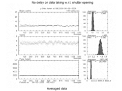
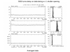
- So far acquisition has been started at the earliest 5000 turns after the shutter open command (corresponding to the moment in time where the shutter is totally open). The following 2 pictures of averaged data illustrate this.
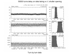
- In the second picture one observers in the first couple of tenthousands of turns some positional fluctuation, which may be caused by a residual vibration in the optics line due to the opening of the shutter. Setting the delay to 50k turns one obtains:
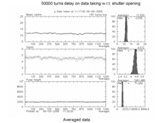
- The turn by turn, averaging and time scan routines for the BSM now all have a delay of 50k turns.
June 14, 2006 (T. Wilksen): Checked out Coldfire device for BSM 23E and reprogrammed it.
- Checked connections and settings for Coldfire device at BSM 23E. Currently the device is known as
CBI-CF02 192.168.1.146(Ethernet access)
CBI-CF02 192.168.1.167 950(Serial line access)
MOXA167-P1 192.168.1.167(Serial line/Terminal server)
- Note that we had to change hostnames for the Coldfire devices due to DNS conventions. The underscore had to be replaced by a hyphen. That has been changed in the boot environment as well as in the server configuration. The current setup for the boot environment is:
FACTORY=Arcturus Networks Inc. REVISION=uC5282 Rev 1.0 4MB External Flash SERIAL=X43283D6C-018BD CONSOLE=ttyS0 KERNEL=0:linux.bin KERNEL_ARGS=root=/dev/rom0 HWADDR0=00:06:3B:00:58:BD FW_VERSION=180001 _0=10000000:400000:RW RAMIMAGE=yes IPADDR0=192.168.1.146 GATEWAY=192.168.1.210 CACHE=on NETMASK=255.255.0.0 NTPSERVER=128.84.46.171 NAMESERVER=128.84.47.200 HOSTNAME=cbi-cf02 - Flashed Coldfire ROM with newest version of CBI_NET server 0.75h for Ethernet based r/o.
July 2006
July 28, 2006 (E.Tanke): Raw data over 150k turns for 1 bunch under CLEO conditions
- Data files are stored on the server under /nfs/cesr/temp/ts101/BSM23E_data/2006/2006_07
- File 00129 for PMT HV=-550V
- File 00132 for PMT HV=-600V
- File 00133 for PMT HV=-650V
- Histograms of these data are shown in this PDF file
- Current limits on the PMT according to JAD:
- The amplifiers on the BSM ADC boards have an input bias current between 20 and 40 uA. I am unsure about the sign but I can try and measure one to clear that up. This corresponds to a signal between 1 and 2 mV at the input of the Current Monitor Board ADC which has a range of +/- 50mV.
- This 1 to 2 mV is the DC offset (temperature drift ~ 0.1% per degree). The signal we want to measure is 1 to 10 uA, or 0.05 to 0.5 mV at the input of the Current Monitor Board ADC (a fraction of the pedestal value).
- There is no specific hardware limit on the current signal, however, only a broken channel should saturate the ADC. It is unlikely that over/under range testing is required.
- Full scale: +/- 50 mV = +/- 1 mA = 16 bits (1 LSB = 1.526 uV = 30.52 nA) ; so 200 counts is ~ 6 microA
- Pedestal: +/- 1 to 2 mV = +/- 20 to 40 uA (ADC dat = 655 to 1311)
- Signal: 0.05 to 0.5 mV = 1 to 10 uA (ADC dat = 32 to 328)
August 2006
August 1, 2006 (M.Palmer, D.Hartill, R.Holtzapple, J.Dobbins, E.Tanke): BSM23E related modifications
- Have swapped the beam splitter pellicle to the CCD optics line in the 23E synch light monitor. Previously had a 92T/8R pellicle --> 50T/50R pellicle. Thus this will roughly halve the light intensity on the CCD while increasing the light to the PMT line by a factor of ~6 (MAP/DHR/RLH)
- Installed 2nd generation timing repeater at 12E ; timing scan shows TglobA needs to be 750 (JAD,EPT)
- HEP BSM23e Measurements [EPT, MP, RH]
PMT      BSM    Pattern                                    Condition
Voltage  File
480V     155    23 bunches + 1 pedestal Before CESR-c fill 10,000 turns/100 turn average
480V     156    23 bunches + 1 pedestal After  CESR-c fill 10,000 turns/100 turn average
480V     157    23 bunches + 1 pedestal After  CESR-c fill Single turn-500 turns
- Found that repeater installed at 12E introduces a one bunch delay. Modified bunch map files to reflect this. Repeat measurements
PMT Voltage BSM File  Pattern                        Condition
480V        162       23 bunches + 2 pedestal        10,000 turns/100 turn average
480V        163       23 bunches + 2 pedestal        Single turn-500 turns
480V        164       23 bunches + 1 pedestal        10,000 turns/100 turn average
480V        165       23 bunches + 1 pedestal        Single turn-500 turns
August 2, 2006 (M.Palmer, E.Tanke): Swapped splitter back to original
- Replaced the beam splitter for the 23E synchlight; previously had 50T/50R (see yesterdays elog entry), reinstalled 92T/8R pellicle
August 3, 2006 (E.Tanke): Measurements during CLEO HEP conditions
- Timing scan, timing step=10 (file 173) for 23 bunches and one pedestal, PMT HV=-550V shows optimum timing is TglobA=600
- With PMT HV=-550V, 23 bunches+1 pedestal, TglobA=600:
- Turn-by-turn data, 500 turns: file 181
- 10,000 turns/100 turn average: file 182
- With PMT HV=-600V, 23 bunches+1 pedestal, TglobA=600:
- Turn-by-turn data, 500 turns: file 183
- 10,000 turns/100 turn average: file 184
- With PMT HV=-650V, 23 bunches+1 pedestal, TglobA=600:
- Turn-by-turn data, 500 turns: file 190
- 10,000 turns/100 turn average: file 191
August 7, 2006 (E.Tanke): Investigation of noisy raw data
- With current CLEO conditions of about 55 mA of total positron current (~2.3 mA per bunch), going beyond -660V on the PMT HV will cause the ADC to be in saturation. Measurements made on August 3rd did not go beyond a PMT HV of -650 V
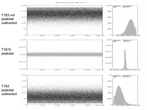
- With PMT HV=-650V, 1 bunch (T1B3) +1 pedestal (T1B10), TglobA=600 for 100k turns of raw data one can see in the plot below (data plotted for the peak channel (GEO 14 or ADC 13)) that there are still 2 distinct bands of pulse heights as a function of turn number (compare to data shown in this PDF file of 28-Jul-2006), which is indicative of timing jitter (the recently installed timing repeater (see 1-Aug-2006 entry) is of the 2nd generation; timing jitter should be largely reduced with the soon to be installed 3rd generation repeater.
August 8, 2006 (D.Hartill, M.Palmer, E.Tanke): Displacement of expander lense
- The expander was moved behind the shutter in order to reduce the image size on the PMT
- Timing scan was made (file 235) with PMT HV=-550V, timing step size of 10; peak timing around TglobA=620
August 8, 2006 (G.Codner, M.Palmer, E.Tanke): MS Ecloud measurements
- Ecloud measurements with following 3 settings for bunches and turns:
- 100 samples of 100 turn averages for all bunches + 1 pedestal (A)
- 1000 samples of 100 turn averages for 1 bunch + 1 pedestal (B)
- 1000 turns, turn by turn for all bunches + 1 pedestal (C)
- 19:10 Measurements with 0.75 mA per bunch, PMT HV=-700V
- A: file 239
- B: file 240
- C: file 241
- 19:25 Raised horizontal tune to 235 kHz and raised chromaticity; Measurements with 0.75 mA per bunch, PMT HV=-750V
- A: file 242
- B: file 243
- C: file 244
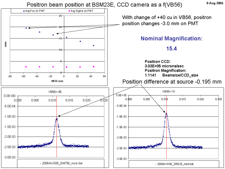
- PMT calibration by bumping beam and comparing with VSIZE data
- To save VSIZE data:
- Kill VSIZE on BD1 display
- Edit programs.dat in main directory; set vsize to no
- run vsize, upon prompt for AUTO, type AUTO
- type the letter d to save data to data file
- type q to quit
- Following are the files corresponding to vbumping settings:
- VBUMPING56=-56, VSIZE=204756, PMT=245
- VBUMPING56=-36, VSIZE=204930, PMT=246
- VBUMPING56=-16, VSIZE=205025, PMT=247 (nominal setting)
- VBUMPING56=4, VSIZE=205115, PMT=248
- VBUMPING56=24, VSIZE=205213, PMT=249
- VBUMPING56=44, VSIZE=205305, PMT=250
- Nominal magnification is shown below:
- To save VSIZE data:
August 14, 2006 (E.Tanke): BSM routines now propose timing as a function of selected PMT HV
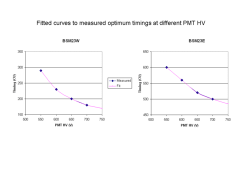
- Similar to BSM23W (see BSM23W 10-Aug-2006 log entry), a fit to BSM23E timing scans has been made. The fitted curve (see below) is now used to propose an optimum timing to the user. The timing will change depending on the PMT HV chosen.
August 15, 2006 (J.Dobbins, E.Tanke): Test of new timing repeater at 12E
- Replaced the timing repeater RevII at 12E for a RevIII and replaced the variable 5V PS for a fixed one.
- Upon testing found that signal on the scope at 23E did not change significantly between the old and the new repeater. Signal at 12E behind the repeater looked ok.
- Upon acquiring data with the DSP, there were unexpected irregularities in the pedestal values. Decided to go back to the old system; in doing so, found that one of the leads of the cable that powers the repeater had a bad connection. Fixed the connection and tested the DSP data again; with the old repeater installed, pedestals were back to normal.
- There was no time left to retest the new repeater with the fixed connection (1 h access)
- After the access, tested the new repeater in the DAQlab (John made up a PS cable for this test). Find that repeater occasionally misses pulses (John will investigate further).
- Verified that BCM filter resistors on front panel PCB are 4kOhm, like at 23W
- Moved measurement files upto and including #311 from the VAX to the server in subdirectories of /nfs/cesr/temp/ts101/BSM23E_data/2006
August 18, 2006 (E.Tanke): New timing repeater installed at 12E
- Profited from an access to re-install the new timing repeater at 12E. The problem seen with it on August 15 had been fixed and the repeater tested in the DAQlab prior to this installation.
- Timing scans at PMT HV=550 V (all bunches, file #319), and subsecently for T1B3 with PMT HV=550V (#320), 600V (#322), 650V (#323) and 700V (#324) show that the optimum timings for these voltages have remained unchanged from the August 14 timing scan.
August 21, 2006 (R.Holtzapple,J.Kern,J.Codner,E.Tanke): MS Beamsize as a function of e- and e+ current
- Measurements for 10k turns averaged data with 100 turn/avg; also logging of FLM data:
- Executable: [cesr.flm.data_log]nflm_dlog.exe
- Input data file: [cesr.flm.data_log]flm_data.inp (or FLM_DATA_2006_08_21.INP)
- Output files on: log3$disk[cesr.flm.dlog]
- Enable execution with: fff vxputn FLM FIT DATA 30 30 0
- Disable execution with: fff vxputn FLM FIT DATA 30 30 1
- Positrons only:
- 0.5 mA, FLM logfile #54
- PMT HV=-650V file #356
- PMT HV=-700V file #355
- 1.0 mA, FLM logfile #53
- PMT HV=-600V file #352
- PMT HV=-650V file #351
- 1.5 mA, FLM logfile #55
- PMT HV=-600V file #358
- PMT HV=-650V file #357
- 2.0 mA, FLM logfile #56
- PMT HV=-600V file #359
- 2.5 mA, FLM logfile #57
- PMT HV=-600V file #360
- 0.5 mA, FLM logfile #54
- Electrons and Positrons:
- 0.5 mA e-,2.5 mA e- , FLM logfile #58
- PMT HV=-600V file #362
- 1.0 mA e-,2.5 mA e- , FLM logfile #59
- PMT HV=-600V file #363
- 1.5 mA e-,2.5 mA e- , FLM logfile #60
- PMT HV=-600V file #366
- 2.9 mA e-,2.5 mA e- , FLM logfile #61
- PMT HV=-600V file #369
- 0.5 mA e-,2.5 mA e- , FLM logfile #58
August 24, 2006 (G.Codner,M.Forster,M.Palmer,E.Tanke) Beam splitters, calibration scan and MS ECLOUD and wiggler
- Beamsplitter work
- Replaced the first beam splitter (CCD line), which was a 92T/8R; replaced it by a 50T/50R
- Replaced the second beam splitter (PMT line), which was a 67T/33R; replaced it by a 50T/50R
- Note that the shutter is followed by a 500nm filter and an expander lens on seperate posts
- File 408: Timing scan at 500V, 2mA, optimum timing=600
- Verified that, like at 23W, turn-by-turn data is clean now !
- Calibration scan with VB56 with CCD and BSM data taking; 2 mA, T1B1, PMT HV=500, timing=600
- VB56=-16, CCD file 040100, BSM file 409
- VB56=-76, CCD file 0430737, BSM file 410
- VB56=-56, CCD file 040859, BSM file 411,
- VB56=-36, CCD file 040957, BSM file 412
- VB56=-16, CCD file 0401054, BSM file 413
- VB56=+4, CCD file 041157, BSM file 414
- VB56=+24, CCD file 041244, BSM file 415
- VB56=+44, CCD file 041331, BSM file 416
- Note that VB56=-16 is the nominal setting
- MS ECLOUD
- Timing scan (file 417) at 550V for 0.5 mA; optimum timing 600
- 0.5 mA, 45 bunches and 1 pedestal, PMT HV=550V, T=600
- File 418: 1k turns of raw data
- File 419: 10k turns of averaged data, 100 turns/avg, 100 averages
- MS Wiggler test, 0.5 mA, 45 bunches and 1 pedestal, PMT HV=550V, T=600
- 6 wigglers at 80% of nominal
- File 420: 10k turns of averaged data, 100 turns/avg, 100 averages
- File 421: 1k turns of raw data
- 6 wigglers at 60% of nominal
- File 422: 10k turns of averaged data, 100 turns/avg, 100 averages
- File 423: 1k turns of raw data
- 6 wigglers at 30% of nominal
- File 424: 10k turns of averaged data, 100 turns/avg, 100 averages (before tune adjustment)
- File 425: 10k turns of averaged data, 100 turns/avg, 100 averages (after tune adjustment)
- File 426: 1k turns of raw data
- 6 wigglers at 0% of nominal; moved mirrors to recenter beam on PMT
- File 427: 10k turns of averaged data, 100 turns/avg, 100 averages
- File 428: 1k turns of raw data
- 6 wigglers at 80% of nominal
August 25, 2006 (E.Tanke) Analysis of yesterdays calibration scan
- Below is shown the beamsize relative to the beamsize for the nominal VB56 setting; one observes that the beam is clipped on the BSM for the two highest VB56 settings.
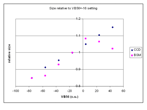
- Based on the positional change between the VB56=-76 and VB56=-16 settings, the magnification factor is 16.1
- Based on the beamsize for both these settings, the magnification factor is 14.5
- Note that the extent of the light on the BSM was close to the PMT size. The expander lens will soon be replaced by one with lower expansion.
August 31, 2006 (R.Holtzapple,J.Kern,E.Tanke) BSM measurements during CLEO conditions (3686 run)
- Parasitic CESR-c Colliding Beams PMT Measurements; 24 bunches HEP, Bunch Pattern ~8x3:
- Bunch 3 Trains 1-8
- Bunch 4 Trains 1-9
- Bunch 5 Trains 2-8
- Measurements made both for electrons and positrons
| Condition | PMT | Turns | Data | Shutter delay |
|---|---|---|---|---|
| 8x3 e+ 100avg | 550 | 10000 | 451 | 50K turns |
| 8x3 e- 100avg | 550 | 10000 | 452 | 50K turns |
| 8x3 e+ Raw | 550 | 500 | 454 | 50K turns |
| 8x3 e- Raw | 550 | 500 | 453 | 50K turns |
| 8x3 e+ Raw | 550 | 10000 | 456 | 50K turns |
| 8x3 e- Raw | 550 | 10000 | 455 | 50K turns |
| T3 B3 e- Raw | 550 | 20000 | 458 | 60K turns |
| 8x3 e+ Raw | 550 | 10000 | 460 | 60K turns |
| 8x3 e- Raw | 550 | 10000 | 461 | 60K turns |
| Train4 b3-5 e+ Raw | 550 | 100000 | 463 | 70K turns |
| Train4 b3-5 e- Raw | 550 | 100000 | 462 | 70K turns |
- Files up to and including file number 449 are now on the server ( /nfs/cesr/temp/ts101/BSM23E_data )
September 2006
September 6, 2006 (M.Palmer, E.Tanke): Modifications to BSM23E optics line
- Replaced the expander lenses in both the east and west PMT optics lines to reduce the magnification by approximately two-thirds f=-25 mm lens replaced with an f=-50 mm lens in each line but with longer moment arm) . In addition replaced the two PMT optics line mirrors in the east with larger aperture mirrors (old mirrors had been an operational limit in the east). Optics alignment was maintained using the laser alignment setup so we should be ready to go this evening.
September 7, 2006 (M.Palmer, L.Schachter, R.Holtzapple, G.Codner, E.Tanke): ECLOUD measurements
- Measurement types
- (a): 100 turn avg, 10k turns total, 45 bunches + 1 pedestal
- (b): 1k turns of raw data, 45 bunches + 1 pedestal
- (c): 10k turns of raw data, selected bunches + 1 pedestal
- Positron measurements 0.80 mA , PMT HV=500V, T=620, selected wigglers off, feedback turned up
- (a): 538
- (b): 539
- (c): 540 (bunches 1,6,11,....41 +1 pedestal)
- Positron measurements 0.80 mA , PMT HV=500V, T=620, selected wigglers off, feedback turned down
- (a): 541
- (b): 542
- Timing scan 543
- Positron measurements 0.25 mA , PMT HV=550V, T=580, selected wigglers off, feedback turned down
- (a): 544
- (b): 545
- (c): 546 (bunches 1,11,21,31,41 +1 pedestal)
- Positron measurements 0.90 mA , PMT HV=500V, T=620, selected wigglers off, feedback turned down
- (a): 547
- (b): 548
- Positron measurements 0.90 mA , PMT HV=500V, T=620, selected wigglers off, feedback turned up
- (a): 549
- (b): 550
- Positron measurements 0.90 mA , PMT HV=500V, T=620, selected wigglers off, feedback turned halfway
- (a): 551
- (b): 552
- Positron measurements 0.90 mA , PMT HV=500V, T=620, selected wigglers off, feedback turned down
- (c): 553 (bunches 1,3,5,7,...,45 + 1 pedestal)
- Positron measurements 1.0 mA , PMT HV=500V, T=620, all wigglers on, feedback turned up
- (a): 557
- (b): 558
- Positron measurements 1.0 mA , PMT HV=500V, T=620, all wigglers on, feedback turned halfway
- (a): 559
- (b): 560
- Positron measurements 1.0 mA , PMT HV=500V, T=620, all wigglers on, feedback turned down
- (a): 561
- (b): 562
- Positron measurements 1.0 mA , PMT HV=500V, T=620, all wigglers on, feedback turned down
- (a): 563
- (b): 564
- Positron measurements 1.0 mA , PMT HV=500V, T=620, all wigglers on, feedback turned up
- (a): 566
- (b): 565
- Positron measurements 1.0 mA , PMT HV=500V, T=620, all wigglers on, feedback turned down
- (c): 567 (bunches 1,6,11,16,21,....,41 +1 pedestal)
- Positron measurements 0.25 mA , PMT HV=550V, T=580, all wigglers on, feedback turned down
- (a): 569
- (c): 570 (45 bunches +1 pedestal)
- Files up to and including file number 519 are now on the server ( /nfs/cesr/temp/ts101/BSM23E_data )
September 18, 2006 (E.Tanke) Calibration scan
- Calibration scan with VB56 with CCD and BSM data taking; 2 mA, T1B1 (single bunch)
- VB56=-16, CCD file 080103, BSM file 611
- VB56=-56, CCD file 080337, BSM file 612
- VB56=-36, CCD file 080500, BSM file 613
- VB56=-16, CCD file 080548, BSM file 614
- VB56=+4, CCD file 080636, BSM file 615
- VB56=+24, CCD file 081724, BSM file 616
- Note that VB56=-16 was the nominal setting
- Based on the positional change between the VB56=-56 and VB56=-16 settings, the magnification factor is 10.4
- Based on the beamsize for both these settings, the magnification factor is 8.9
- Files up to and including file number 616 are now on the server ( /nfs/cesr/temp/ts101/BSM23E_data )
September 25, 2006 (T. Wilksen) CBI_NET Ethernet R/O
- Flashed Coldfire ROM with newest RTEMS CBI_NET server version 0.80.
September 26, 2006 (M.Palmer, L.Schachter, G.Codner, M.Pivi, D.Rice, E.Tanke): ECLOUD measurements at CHESS energy
- Measurement types
- (a): 100 turn avg, 10k turns total, 45 bunches + 1 pedestal
- (b): 1k turns of raw data, 45 bunches + 1 pedestal
- (c): 10k turns of raw data, 45 bunches + 1 pedestal
- Positron measurements 0.5 mA , PMT HV=450V, T=700
- (a): 657
- (b): 658
- Positron measurements 0.85 mA , PMT HV=450V, T=700
- (a): 659
- (b): 660
- (c): 662
October 2006
October 02, 2006 (E.Tanke): New BSM_V1 executable in DEV directory
- There is now a new bsm_v1 executable, which generates bsmYYY_cur_xxxx.dat files that contain more info about the machine status and saveset numbers.
- This executable also has linked to it a first generation CBI_NET software, allowing for ethernet transfer (for "raw" data only)
- Note that this executable is located in the [cesr.palmer.ts101.bsm.dev] directory
October 03, 2006 (M.Forster, R.Holtzapple, J.Kern, E.Tanke): Beamsize measurements at CHESS energy under different coupling conditions
- Measurement types
- (a): 100 turn avg, 10k turns total
- (b): 1k turns of raw data
- Positron measurements, single bunch T1B1 5 mA
- (a): 702
- (b): 703
- Change coupling, single bunch T1B1 5 mA
- (a): 704
- (b): 705
- Add bunches: T1B1..B5 -> T4B1..B5 positrons 7 mA/bunch; T5B1..B5 -> T9B1..B5 electrons 7 mA/bunch; Positron measurements:
- (a): 706
- (b): 708
- Change coupling; Positron measurements:
- (a): 710
- (b): 712
- Change coupling; electrons kicked out of the machine; Positron measurements:
- (a): 714
- (b): 716
- Change coupling; Positron measurements:
- (a): 718
- (b): 719
- Add electron bunches: T5B1..B5 -> T9B1..B5 electrons 3.5 mA/bunch; Positron measurements:
- (a): 720
- (b): 722
- Change coupling; Positron measurements:
- (a): 724
- (b): 726
- Only keep electron bunches: T8B1..B5 -> T9B1..B5 electrons 9 mA/bunch; Positron measurements:
- (a): 728
- (b): 730
- Change coupling; Positron measurements:
- (a): 732
- (b): 734
October 10, 2006 (M.Forster, R.Holtzapple, J.Kern, E.Tanke): Beamsize measurements at CHESS energy under different coupling conditions
- Measurement types
- (a): 100 turn avg, 10k turns total
- (b): 1k turns of raw data
- First measurements, 9x5, positrons only, 4.75 mA/bunch
- (a): 752
- (b): 753
- Change to poorly corrected coupling
- (a): 754
- (b): 755
- Change to well corrected coupling
- (a): 756
- (b): 757
- Adding electrons 9x5 1.5 mA/bunch; Positron measurements:
- (a): 758
- (b): 760
- Change to poorly corrected coupling; Positron measurements:
- (a): 762
- (b): 764
- Change to well corrected coupling; Positron measurements:
- (a): 766
- (b): 768
- Increase electron bunch current to 3 mA/bunch; Positron measurements:
- (a): 770
- (b): 772
- Change to poorly corrected coupling; Positron measurements:
- (a): 774
- (b): 776
- Change to well corrected coupling; Positron measurements:
- (a): 778
- (b): 780
- Increase electron bunch current to 4.75 mA/bunch; Positron measurements:
- (a): 782
- (b): 784
- Electrons are falling out. Refill electrons (and positrons); Positron measurements:
- (a): 786
- (b): 788
- Change to poorly corrected coupling; Positron measurements:
- (a): 790
- (b): 792
- Change to well corrected coupling; Positron measurements:
- (a): 794
- (b): 796
- Files up to and including file number 749 are now on the server ( /nfs/cesr/temp/ts101/BSM23E_data )
October 12, 2006 (R.Holtzapple, J.Kern, E.Tanke): Beamsize measurements at CHESS energy
- Measurement types
- (a): 100 turn avg, 10k turns total
- (b): 1k turns of raw data
- (c): 10k turns of raw data
- First measurements, positrons 9x5 and electrons 9x5
- Positron measurements:
- (a): 800
- (b): 802
- Adjust SYLTE mirrors; Positron measurements:
- (a): 804
- (b): 806
- (c): 807
- After tests conducted by JPS (which involved moving the mirrors), mirrors set back to initial set values; Positron measurement:
- (c): 810
- Files up to and including file number 810 are now on the server ( /nfs/cesr/temp/ts101/BSM23E_data )
October 17, 2006 (J.Codner,M.Forster, R.Holtzapple, J.Kern, E.Tanke): Beamsize measurements at CHESS energy under different coupling conditions
- Measurement types
- (a): 100 turn avg, 10k turns total
- (b): 1k turns of raw data
- First measurements after down recovery, 9x5, positrons and electrons, 4.75 mA/bunch ; positron measurements:
- (a): 821
- (b): 823
- Set initial settings of 10-Oct-2006 (saveset 112793) and measure electrons only
- Reset to initial settings with electrons and positrons; Positron measurements:
- (a): 831
- (b): 833
- Change to well corrected coupling; Positron measurements:
- (a): 835
- (b): 837
- Change to poorly corrected coupling; Positron measurements:
- (a): 839
- (b): 841
October 24, 2006 (M.Forster, R.Holtzapple, J.Kern, E.Tanke): Beamsize measurements at CHESS energy under different coupling conditions
- Measurement types
- (a): 100 turn avg, 10k turns total
- (b): 1k turns of raw data
- First measurements after down recovery, 9x6, positrons and electrons, 3.7 mA/bunch ; positron measurements:
- (a): 852
- (b): 854
- Measure with positrons only in CESR
- (a): 859
- (b): 858
- Change to poorly corrected coupling; Positron measurements:
- (a): 860
- (b): 861
- Change to well corrected coupling; Positron measurements:
- (a): 862
- (b): 863
- Measure with positrons AND electrons in CESR; Positron measurements:
- (a): 865
- (b): 867
- Change to poorly corrected coupling; Positron measurements:
- (a): 870
- (b): 872
- Change to well corrected coupling; Positron measurements:
- (a): 874
- (b): 876
- Both RF phases changed by +4 cu; Positron measurements:
- (a): 878
- (b): 880
October 31, 2006 (G.Codner, M.Forster, R.Holtzapple, J.Kern, E.Tanke): Beamsize measurements at CHESS energy under different coupling conditions, V tune change
- Measurement types
- (a): 100 turn avg, 10k turns total
- (b): 1k turns of raw data
- First measurements after down recovery, 9x6, positrons and electrons, 4 mA/bunch ; positron measurements:
- (a): 889
- (b): 891
- Change to mangled coupling; Positron measurements:
- (a): 893
- (b): 895
- Change to well corrected coupling; Positron measurements:
- (a): 897
- (b): 899
- Change V tune to 1 kHz below nominal ; Positron measurements:
- (a): 901
- (b): 903
- Change V tune to 1 kHz above nominal ; Positron measurements:
- (a): 905
- (b): 907
- Change V tune to 2 kHz below nominal ; Positron measurements:
- (a): 909
- (b): 911
Edit | Attach | Print version | History: r74 < r73 < r72 < r71 | Backlinks | View wiki text | Edit wiki text | More topic actions
Topic revision: r74 - 21 May 2007, EugeneTanke
 Copyright © by the contributing authors. All material on this collaboration platform is the property of the contributing authors.
 Ideas, requests, problems regarding CLASSE Wiki? Send feedback

