You are here: CLASSE Wiki>ACC/Bunch Web>BSMXB1Log_2006 (13 Jun 2008, JimAlexander)Edit Attach
CHESS X-Ray BSM hutch B1 Electronic Logbook 2006-2007
17 May 2025 - 22:57May 2008
Jim's log book (32pg, pdf format) from the first CesrTA running time, May 19-23 is hereNovember 29th, 2007 (Jim, Jake, & Deb)
November 2007
November 29th, 2007 (Jim, Jake, & Deb)
- -1.0006 with slx between 34..0 and 40.0
- step up 1mm at a time (umvr slz 1)
November 26th, 2007 (Jim & Deb)
- We now are biassing the silicon photodiode. DC current depends on bias (indicates finite carrier lifetime??). With 10V reverse bias we see 9-10uA DC current in the present set up (with multilayer mirrors). Ibeam = 245mA.
- For the above result we have the motors in the following positions: 11.5000 34.0000 -1.0984 1.3000 1.2051. These correspond to slz slx monx monu monz, respectively.
November 23rd, 2007 (Jim & Jake)
- AlignmentStudies
- layers of Reynolds wrap aluminum foil reduces IDC from 15.6uA to 6.1uA
- Note: thickness of foil is thought to be about 20um; composition is 98.5% aluminum and rest is iron and silicon (see Reynolds web pages!)
- Deduce approximate beam energy from these facts: answer is 13.5keV but this is sensitive to thickness. if we assume 10um thick, answer is 10.7 keV
November 22th, 2007 (Jim & Jake)
- Happy Thanksgiving!
- First thing: find the beam, establish coordinate system. Right now the beam is roughly centered on the "origin" of the graph paper when the slx, slz motors are set to: (slx,slz)=(34.0,11.5)
November 20th, 2007 (Jim A)
- Today we will check the integrity of the CESR timing cable to B1.
- CHESS guys are building the optics box for the multilayer mirror monochromator and zone plate. Will also allow use of pinhole.
January 2006
January 20, 2006 (E.Tanke): CHESS X-ray BSM
- This week cables have been pulled to CHESS hutch B1 for CHESS X-ray BSM experiments. A database node has been added to talk to the DSP at this location: BSM PROC XXX 3, where XXX=ADR, PKT and DAT.
- With a test signal (pulse length ~ 4ns) supplied by a LeCroy pulse generator connected to the diode board (no diode mounted yet, instead a 50 Ohm resister to ground and a 1.2 pF to the input were mounted), the following response was found:
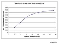
January 30, 2006 (J.Alexander, P.Revesz, M.Palmer, N.Adam, R.Gray, N.Taylor, E.Tanke): First results with a single diode in the beam
- With a GaAs diode, currents in the nA range were measured using the picoA-meter, well below the 50 nA noise floor of the amplifier.
- Then the GaAs diode was replaced by a silicon one; currents in the microA range were measured (Jim has the exact numbers). With the scope we were unable to see any bunch structure, but were able to see a DC shift in the signal (signal read from and amplified by the picoA-meter).
- Subsequently, the silicon diode got hooked up to the DSP; a time scan over all bunches yielded the following results:
- As it stands, the bunch signal is too small in amplitude to be seen as a function of time with the DSP. The DC shift is most certainly in part due to the "long" leads that were used for hooking up the diode (they were used for debugging the hardware).
April 2006
April 20, 2006 (C.Strohman): New XBSM module
- The original FLM module has been updated for use as the XBSM module. This consisted of replacing the I/O board, installing a ColdFire module, and configuring the Xilinx with the latest BSM code.
- The ColdFire module is CBI_CF03 (192.168.1.147).
May 2006
May 17, 2006 (J.Alexander et al): XBSM machine study status
- On Friday and Monday, Eugene and Peter Revesz and I got things set up in the B1 hutch, setting and aligning the collimators, and making preliminary measurements of photodiode currents in the silicon photodiode. Eugene has also set up the verified the DSP operation down there. The apertures were set/measured with feeler gauges of various sorts.
- To summarize the details we have the following:
- Bend magnet radius: 31.654m
- Beam energy: 5.3 GeV
- Beam currents: typically around 100-200mA; 4-hour runs.
- SR source-to-slit distance: 10.5m
- sum of vacuum windows: 0.762mm Be + Aluminum layer (thickness= 1um???)
- slit horizontal aperture: 1.25mm (+/- 0.05 or so??)
- slit vertical aperture: 40um (+/- 5um, I would guess)
- slit-to-detector distance: 2.9 m
- Additional filters used in various combinations:
- helium(?)-filled drift tube, about 2.5m
- 0.5, 1.0, 1.5 inch aluminum
- 3/16 inch copper
- The normalization seems to be understood now. Here are some results for the silicon photodiode:
I(e-)           Filter          I(dark)         I(exposure)

165mA           1.5inAl         17nA(*)         165nA
160mA           1.5inAl         19pA            146nA
188mA           1.5inAl         20pA            157nA
188mA           1.5inAl&3/16Cu  20pA            1.85nA
188mA           1.5inAl&3/8Cu   20pA            0.25nA
166mA           2.5inAl         20pA            18.5nA
166mA           1.5inAl         20pA            138nA
- The first measurement includes a non-negligible dark current due to other LEDs in the hutch that we subsequently taped over.
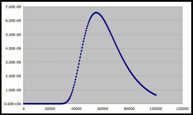
- Peter ran an XOP calculation corresponding to the conditions of the first measurement, and predicts (well, postdicts) a diode current of 150nA (assuming 150um silicon collection depth) or 450nA (assuming 300um silicon collection depth). I believe the effective silicon depth is about 250um. Incidentally the silicon is unbiassed in these measurements; that shouldn't matter for a DC current measurement.
- The conclusion is that we measure and compute a diode current that agree within a factor of two. This is a significant improvement over the factor 10^5 discrepancy that we had in January.
- Here is a graph of the diode current versus xray energy, from the XOP calculation. (Read the vertical axis as dI/dE in units of Amps/502eV. The integral of this curve is the current quoted above.) The main thing you'll notice is that because of heavy filtering by the aluminum(ium) blocks, the photodiode is mainly seeing xrays in the 40-60keV range. This is of course rather higher than we anticipate using with the GaAs diodes.
- diode current versus Xray energy:
- Installed GaAs diodes; find following response with the picoA meter for 195 mA of electrons in CESR and using diode #3 (wires 8 and 9):
- Dark current is < 0.8 pA
- With 1" Al filter: -2.1 nA
- Without filter: -4.5 uA
- Plugged the wires 8 and 9 of diode 3 directly into a DSP interface board. One can observe the 5x5 electron bunches that were in CESR at the time of measurement on the plot below, obtained through a time scan:
May 18, 2006 (J.Alexander, M.Billing, E.Tanke): XBSM machine study status
- Hooked the signal from the GaAs diode up to a Tektronix 7613 scope with a 7S11 type S-4 sampling head. Able to see a rise time of about 300 ps (note that the signal cabling will need to be changed in order to get a more accurate number). The trigger used was "CESR timing", available in the B1 hutch. Cable was added to get the needed delay to the scope.
May 22, 2006 (J.Alexander, E.Tanke): XBSM machine study status
- Hooked up new silicon diode, not taped over; picoA meter response:
- dark current -0.84 nA
- -1.33 mA with Xray beam (CESR e- beam current 161 mA)
- Hooked up old silicon diode (the one used last week), not taped over; picoA meter response:
- dark current -0.81 nA
- -1.3 mA with Xray beam (CESR e- beam current 160 mA)
- Old silicon diode with 2 layers of black tape and diodes of fan control covered; picoA meter response:
- dark current -0.021 nA
- -0.77 mA with Xray beam (CESR e- beam current 160 mA)
- Old silicon diode with 2 layers of black tape and fluorescent material in front of it and diodes of fan control covered; picoA meter response:
- dark current -0.028 nA
- -0.028 mA with Xray beam (CESR e- beam current 159 mA)
- Hooked up GaAs diode with new cable (RG214); picoA meter response:
- dark current < -1 pA
- -4.0 uA with Xray beam (CESR e- beam current 196 mA)
- Scope response with this new RG214 cable not better than what was seen last Friday.
- Hooked up GaAs diode to the DSP. Timed in the bunches with peak at Tglob=1380 and with T1B1=DSP bunch # 137, amplitude ~ 1000 ADC counts for Ie-=180 mA
- Vertical scan with diode, raw data over 100 turns; T5B1 + 1 pedestal; step size 50 microns, files:
- bsmx_mr_2006_05_22_1525.dat
- bsmx_scrz_2006_05_22_1525.dat
- bsmx_cur_2006_05_22_1525.dat
- Vertical scan with diode, raw data over 1 turn; T5B1 + 1 pedestal; step size 50 microns, files:
- bsmx_mr_2006_05_22_1540.dat
- bsmx_scrz_2006_05_22_1540.dat
- bsmx_cur_2006_05_22_1540.dat
- Vertical scan with diode, raw data over 100 turns; T5B1 + 1 pedestal; step size 20 microns, files:
- bsmx_mr_2006_05_22_1555.dat
- bsmx_scrz_2006_05_22_1555.dat
- bsmx_cur_2006_05_22_1555.dat
- Horizontal scan with diode, raw data over 100 turns; T5B1 + 1 pedestal; step size 100 microns, files:
- bsmx_mr_2006_05_22_1605.dat
- bsmx_scrx_2006_05_22_1605.dat
- bsmx_cur_2006_05_22_1605.dat
- Note: scan range too small
- Horizontal scan with diode, raw data over 100 turns; T5B1 + 1 pedestal; step size 100 microns, files:
- bsmx_mr_2006_05_22_1615.dat
- bsmx_scrx_2006_05_22_1615.dat
- bsmx_cur_2006_05_22_1615.dat
- Results are in the plot below:
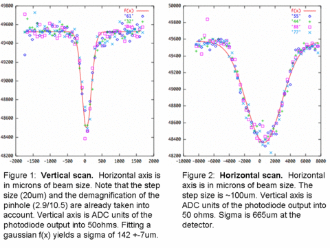
- The vertical beamsize at the source is given by the relationship
- Vertical scan with diode, raw data over 100 turns; T5B1 + 1 pedestal; step size 50 microns, files:
(Vsize)**2 = (beta*Ev)**2 + (eta*Sig_E/E)**2 [1]
-
- With CESRV info for the current CHESS lattice (CHESS_20050617) we find Ev = 1% * Eh = 1.314E-09 and Sig_E/E=6.573E-04 as well as beta=16.2321 m and eta=-0.0025m. Entering these data in [1] yields Vsize=145.8 um, which is close to the 142 um measured.
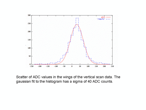
- In order to determine the baseline noise, one can look at the scatter of ADC values in the wings of the vertical scan data (see plot below). The pedestal subtracted signal is about 1027 ADC counts and the gaussian fit to this histogram has a sigma of 37.8 ADC counts. This means a S/N of ~ 27.2, which seems consistent with the eye-ball sense of the scan plots. Also, the average signal (the ~1000 ADC counts) per passing bunch corresponds to 350fC, which translates to about 10MeV. If we, in round numbers, say that all photons are 10keV (a rough approximation) then there are about 1000 photons per bunch passing,... which has a statistical variation of 1/sqrt(1000), ie close to 1 part in 25. This would seem to suggest that our noise is dominated by photon counting statistics.
May 24, 2006 (E.Tanke): XBSM machine study status
- Hooked up all 3 GaAs diodes to the DSP (wires (1,3) to "PMT" channel 24, (4,6) to "PMT" channel 23, (9,8) to "PMT" channel 22)and measured T5B1:
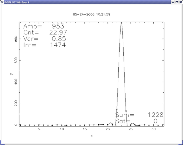
May 25, 2006 (J.Alexander, E.Tanke): XBSM machine study status
- Took out the 40 um slit. Response of the 3 diodes is below:
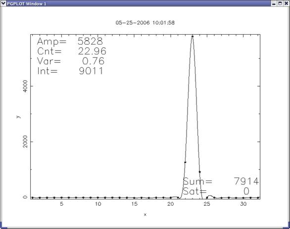
- Hooked up diode 3 (wires8,9) to picoA meter; total current now 23.3 uA (after centering) for Ie-=163 mA
May 26, 2006 (E.Tanke): XBSM machine study status
- Yesterday we started running without slit; at the time of writing this (4:20 pm) the diode we are measuring with the picoA meter still works (reading: ~ 22.8 uA for Ie-=168 mA)
September 2006
September 25, 2006 (T. Wilksen): CBI_NET Ethernet R/O
- Flashed Coldfire ROM with newest CBI_NET server version 0.80. Verified that r/o of static DSP RAM works through CBI_NET interface from and to lnx180c (Linux) and cesr28 (VMS).
- The current installed Coldfire module is cbi-cf06, with ip address 192.168.1.151. It is attached to the Moxa server 192.168.1.177, port 950.
November 2006
November 17, 2006 (J.Alexander, E.Tanke): Tests with Hamamatsu diode array in CHESS hutch B1
- Spec sheet of the Hamamatsu-9494-512 diode array can be found here
- The diode size, called "height" on the Hamamatsu web page, is specified there as 25 microm.
- Motor drives:
- Upstream: sx (horizontal) and sz (vertical)
- Downstream: scrx (horizontal) and scrz (vertical)
- Measurements using the picoAmeter with:
- one of the GaAs diodes used in May 2006 (connected to wires 4,6) --> 300 pA (without filter, not accurately optimized)
- Hamamatsu diode connected to ADC0 --> 1.25 nA (with 0.5" filter, with fluorescent screen)
- Hamamatsu diode connected to ADC0 --> 37 nA (without filter, dark current 5-10 pA, with fluorescent screen)
- Silicon diode --> 0.575 microA (with 1" filter)
- Silicon diode --> 31 microA (without filter, no positional optimization))
- Silicon diode --> 2.2 microA (with 0.5" filter)
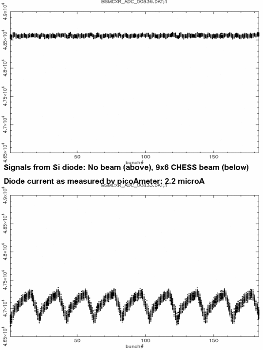
- Timescans using BSM_V1 ind [CESR.PALMER.TS101.DEV] directory for silicon diode and 0.5" filter, without and with beam:
- The 9 trains can be observed but signal is small.
November 18, 2006 (J.Alexander, E.Tanke): Follow up of tests with Hamamatsu diode array in CHESS hutch B1
- Beam current 192 mA e-, beam energy 5.2912 GeV
- Measurements with silicon diode
- PicoAmeter measurement with new Si diode, 3.2 microA (0.5" Al)
- PicoAmeter measurement with new Si diode, 260 microA (no filter, with positional optimization (needed, as after placing the filter, a shift in position of the light on the diode was observed))
- Measurements with old GaAs diode
- One of the GaAs diodes used in May 2006 (connected to wires 4,6) --> 40-50 nA (0.5" Al)
- Same GaAs diode --> 390 nA (no filter)
- Measurements with Hamamatsu GaAs diodes (note: do not forget to make ground connection on PCB)
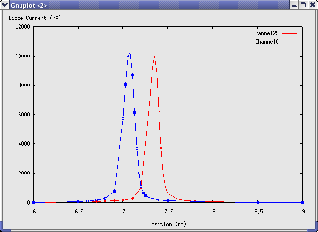
- Diode connected to ADC29 --> more than 10 microA (without fluorescent screen, without filter, dark current < 10 pA) (see scan below)
- Diode connected to ADC12 --> confirmed that it is connected to ground on PCB
- Diode connected to ADC0 --> more than 10 microA (without fluorescent screen, without filter, dark current < 10 pA)(see scan below)
- Final optimization with diode connected to ADC0 yields 11 microA for an e- beam current of 215 mA
- Hamamatsu-9494-512.pdf: Hamamatsu-9494-512.pdf
Edit | Attach | Print version | History: r33 < r32 < r31 < r30 | Backlinks | View wiki text | Edit wiki text | More topic actions
Topic revision: r33 - 13 Jun 2008, JimAlexander
 Copyright © by the contributing authors. All material on this collaboration platform is the property of the contributing authors.
 Ideas, requests, problems regarding CLASSE Wiki? Send feedback
