BSM23W Vertical Beamsize Monitor Electronic Logbook 2005
09 Mar 2025 - 11:55
- BSM23W Vertical Beamsize Monitor Electronic Logbook 2005
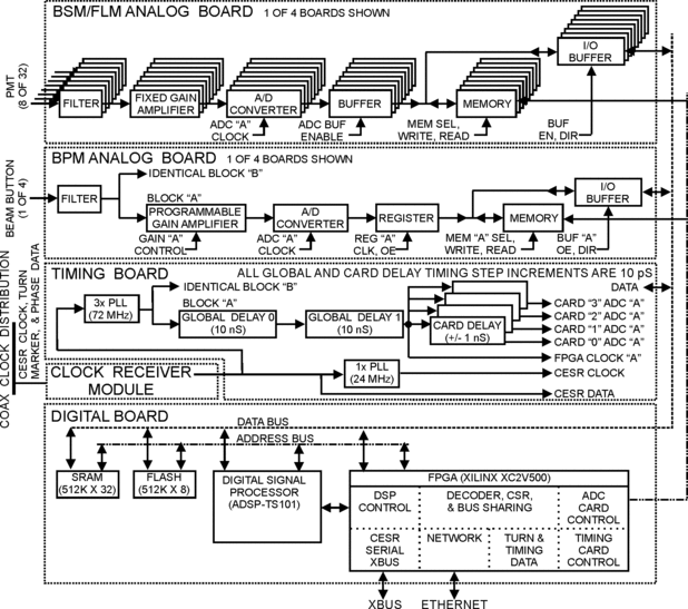
- Hardware Layout
- April 2005
- April 22, 2005 (M. Palmer): Installation of Optics Rail
- April 22, 2005 (M. Palmer for E. Tanke): BSM Module Testing Status
- April 25, 2005 (M. Palmer): Alignment and Response Check of Bunch-by-Bunch Optics Line
- April 25, 2005 (M. Palmer): Notes on Operation of H7260
- April 25, 2005 (M. Palmer/M. Billing): XBUS Assignments for 23W Electronics
- April 25, 2005 (J. Dobbins): PMT Channel Map
- April 25, 2005 (M. Palmer for E. Tanke): Update on BSM Modules Testing Status
- April 26, 2005, 0800-1000 (M. Palmer, J. Dobbins, C. Strohman, E. Tanke w/help from M. Comfort and M. Carrier): Installation
- April 26, 2005, 1000-1300 (J. Dobbins, M. Palmer, C. Strohman, E. Tanke): Communications/Grounding/Noise Checks
- April 26, 2005, 1645-1800 (M. Billing, M. Palmer, E. Tanke, L. Wilkins):
- April 26, 2005, 2100-2300 (M. Palmer, C. Strohman, E. Tanke): Initial Data Attempt
- April 27, 2005 (M. Palmer): 23W BSM Bunch Table
- April 27, 2005 (E.Tanke, M. Palmer): First attempts to acquire raw data
- April 28, 2005 (E.Tanke): Output data file format changes and additional output
- April 29, 2005 (E.Tanke): New BSM data using averaging
- May 2005
- May 04, 2005 (M. Palmer): PMT HV
- May 04, 2005 (M. Palmer, G. Codner, E. Tanke): Beam studies with BSM 23 W
- May 09, 2005 (E. Tanke): Data of 4-May-2005 beam study with BSM 23 W now on fileserver
- May 12, 2005 (E. Tanke): Data of 10-May-2005 beam study with BSM 23 W now on fileserver
- May 16, 2005 (E. Tanke): Plots presented at 13-May-2005 Machine Study meeting
- May 17, 2005 (E. Tanke): Machine study of 17-May-2005 with BSM 23 W
- May 20, 2005 (E. Tanke): Plots presented at 20-May-2005 Machine Study meeting
- May 24, 2005 (E. Tanke): Machine study of 24-May-2005 with BSM 23 W
- May 27, 2005 (E. Tanke): Plots presented at 27-May-2005 Machine Study meeting
- May 31, 2005 (M. Palmer, E. Tanke): Machine study of 31-May-2005 with BSM 23 W
- June 2005
- Jun 03, 2005 (E. Tanke): Plots presented at 03-Jun-2005 Machine Study meeting
- June 10, 2005 (E. Tanke): BSM23W Bunch Map
- June 20, 2005 (M. Palmer, E. Tanke, D. Hartill): Check of Electron Synch Light Optics
- June 21, 2005 (M. Palmer, E. Tanke)
- June 22, 2005 (M. Palmer, E. Tanke) Changes to Electron Synch Light Box Beamsplitters at 23W
- June 23, 2005 (M. Palmer, E. Tanke) Bunch-by-Bunch Optics Line for Electron Synch Light Box at 23W
- June 24, 2005 (M. Palmer, E. Tanke) Bunch-by-Bunch Optics Line for Electron Synch Light Box at 23W
- June 25, 2005 (M. Palmer, E. Tanke) Bunch-by-Bunch Optics Line for Electron Synch Light Box at 23W
- June 27, 2005 (M. Palmer, M. Billing, E. Tanke, A. Wolski) Damping Studies
- June 28, 2005 (M. Palmer, M. Billing, E. Tanke, A. Wolski) Damping Studies
- July 2005
- July 8, 2005 (E. Tanke) Testing of BSM#2
- July 13, 2005 (M. Palmer, E. Tanke) Testing of TEST_SUM10 on BSM23W
- July 19, 2005 (M. Palmer, M. Billing, E. Tanke) Damping Studies and Checks of CHESS Conditions
- July 20, 2005 (M. Palmer, E. Tanke) Measurements under CHESS conditions
- July 21, 2005 (M. Palmer, E. Tanke) Measurements under CHESS conditions
- July 26, 2005 (M. Palmer, E. Tanke, A. Wolski) Single bunch damping studies with BSM23W
- August 2005
- September 2005
- September 14 , 2005 (M. Billing, M.Palmer, E. Tanke) BSM23W work and MS
- September 15 , 2005 (M. Billing, M.Palmer, E. Tanke) BSM23W work and MS
- September 21 , 2005 (M. Billing, M.Palmer, E. Tanke) BSM23W work and MS
- September 28 , 2005 (M. Billing, M.Palmer, E. Tanke) BSM23W work and MS
- October 2005
- November 2005
Hardware Layout
April 2005
April 22, 2005 (M. Palmer): Installation of Optics Rail
Installed rail for bunch-by-bunch optics at 23W (e- synchrotron light box), MAP/Riggers.
Rail is described in LEPP drawing 6048-133. Drilled 2 holes in optics box base plate (for 2 rail slots nearest beam-splitter mount) which we threaded for 1/4-20 screws. Intention was to use cap-head screws going down through rail and screwing into base. Unfortunately hand-drilling could not give good enough alignment. Ended up opening slots by +/-0.040", making holes in base-plate thru holes, placing nuts in top of slots, and screwing up from the bottom. Ultimately able to install and align rail to existing CCD optics rail by end of the access, MAP/MJS.
Installed uncoated pellicle beam-splitter, 500+/-25 nm filter, cylindrical lense. Installed R5600 PMT approximately 8.5" from lense. MAP
April 22, 2005 (M. Palmer for E. Tanke): BSM Module Testing Status
*
DCoffset.doc: Exploration of observed signal offsets with various grounding and power supply configurations.
April 25, 2005 (M. Palmer): Alignment and Response Check of Bunch-by-Bunch Optics Line
Starting Mirror Positions:
- CSRSYLTE CON 1 (horizontal tilt): 721 CU
- CSRSYLTE CON 2 (vertical tilt): 487 CU
- x position (TV monitor reticle): +1.0 mm
- y position (TV monitor reticle): +3.0 mm
NOTE: Discover that moving mirror horizontally in this region has a localized vertical "jump" near centered beam (this is not a coupling between the 2 dimensions but appears to be a bad spot in the mirror actuator)
After some initial scanning and slowly raising the PMT HV, find that can see bunches fairly near the initial settings. Maximum signal is 25 mV with -700V on PMT.
Scans:
April 25, 2005 (M. Palmer): Notes on Operation of H7260
- H7260-04.pdf: Hamamatsu Datasheet for H7260 (applicable parameters are for model H7260K)
- The HV limit for the H7260K is -900V. Administrative limit will be -800V for now.
April 25, 2005 (M. Palmer/M. Billing): XBUS Assignments for 23W Electronics
April 25, 2005 (J. Dobbins): PMT Channel Map
Map between digital front-ends (4 cards, channels 0-7) and PMT channels (1-32):
| Readout Channel |
Card |
Card Ch |
PMT Channel |
Comment |
CMB Channel |
| 00 |
0 |
0 |
24 |
|
09 |
| 01 |
0 |
1 |
22 |
|
11 |
| 02 |
0 |
2 |
20 |
|
13 |
| 03 |
0 |
3 |
18 |
|
15 |
| 04 |
0 |
4 |
15 |
|
18 |
| 05 |
0 |
5 |
13 |
|
20 |
| 06 |
0 |
6 |
11 |
|
22 |
| 07 |
0 |
7 |
09 |
|
24 |
| 08 |
1 |
0 |
23 |
|
10 |
| 09 |
1 |
1 |
21 |
|
12 |
| 10 |
1 |
2 |
19 |
|
14 |
| 11 |
1 |
3 |
17 |
|
16 |
| 12 |
1 |
4 |
16 |
|
17 |
| 13 |
1 |
5 |
14 |
|
19 |
| 14 |
1 |
6 |
12 |
|
21 |
| 15 |
1 |
7 |
10 |
|
23 |
| 16 |
2 |
0 |
26 |
|
02 |
| 17 |
2 |
1 |
28 |
|
04 |
| 18 |
2 |
2 |
30 |
|
06 |
| 19 |
2 |
3 |
32 |
Top |
08 |
| 20 |
2 |
4 |
01 |
Bottom |
25 |
| 21 |
2 |
5 |
03 |
|
27 |
| 22 |
2 |
6 |
05 |
|
29 |
| 23 |
2 |
7 |
07 |
|
31 |
| 24 |
3 |
0 |
25 |
|
01 |
| 25 |
3 |
1 |
27 |
|
03 |
| 26 |
3 |
2 |
29 |
|
05 |
| 27 |
3 |
3 |
31 |
|
07 |
| 28 |
3 |
4 |
02 |
|
26 |
| 29 |
3 |
5 |
04 |
|
28 |
| 30 |
3 |
6 |
06 |
|
30 |
| 31 |
3 |
7 |
08 |
|
32 |
April 25, 2005 (M. Palmer for E. Tanke): Update on BSM Modules Testing Status
-
- DCoffset2.doc: Updated studies of signal offsets in various power supply and grounding configurations.
April 26, 2005, 0800-1000 (M. Palmer, J. Dobbins, C. Strohman, E. Tanke w/help from M. Comfort and M. Carrier): Installation
- Installed all remaining cabling at 23W
- SXIO cable
- Timing cable
- DSP Power Disable ECO cable
- HV cables
- Connected timing cable run to end of BPM segment at 12W. Now terminated at 23W.
- Installed electronics underneath 23W light box
- Installed 32 channel linear PMT array
- Moved expander lense (f = -50 mm) closer to beam-splitter pellicle
- Face of PMT approx 7.5" (= 190 mm) from expander lense (M ~ 3.6)
April 26, 2005, 1000-1300 (J. Dobbins, M. Palmer, C. Strohman, E. Tanke): Communications/Grounding/Noise Checks
- EPT verified that we could talk to the BSM Readout Module
- Then conducted a series of noise checks to determine whether grounding was reasonable
- Initially observed sporadic large noise spikes
- Ultimately did 2 things:
- Made sure PMT not grounded to box
- Placed a ground braid between the power supply box (6048-119) and the DSP module
- Verify that noise levels look reasonable after attach HV cable to power supply in control room.
- Attach noise study document here
April 26, 2005, 1645-1800 (M. Billing, M. Palmer, E. Tanke, L. Wilkins):
- EPT finds that we cannot disable power to DSP module
- MAP/LMW check hardware
- MGB ultimately finds that database address incorrect. Everything works after fix and database refresh
April 26, 2005, 2100-2300 (M. Palmer, C. Strohman, E. Tanke): Initial Data Attempt
- Set PMT HV to -600V
- Run channel-by-channel timing scan and immediately see signal on detector!!!
- bsm_bunch_struct.pdf: Filled Bunches Plot
April 27, 2005 (M. Palmer): 23W BSM Bunch Table
Dump of timing scan ntuple.
T1B1 e- corresponds to DSP Bunch = 39
| Event |
CH |
BUN |
TSTEP |
TIME |
AVG |
| 138376 |
12. |
0. |
27. |
7.6032 |
44681. |
| 138439 |
12. |
1. |
27. |
7.6032 |
45146. |
| 138502 |
12. |
2. |
27. |
7.6032 |
45821. |
| 140833 |
12. |
39. |
27. |
7.6032 |
45225. |
| 140896 |
12. |
40. |
27. |
7.6032 |
45169. |
| 140959 |
12. |
41. |
27. |
7.6032 |
45324. |
| 141022 |
12. |
42. |
27. |
7.6032 |
45153. |
| 141085 |
12. |
43. |
27. |
7.6032 |
45381. |
| 142093 |
12. |
59. |
27. |
7.6032 |
45097. |
| 142156 |
12. |
60. |
27. |
7.6032 |
45046. |
| 142219 |
12. |
61. |
27. |
7.6032 |
45029. |
| 142282 |
12. |
62. |
27. |
7.6032 |
45311. |
| 142345 |
12. |
63. |
27. |
7.6032 |
46122. |
| 143353 |
12. |
79. |
27. |
7.6032 |
45039. |
| 143416 |
12. |
80. |
27. |
7.6032 |
44927. |
| 143479 |
12. |
81. |
27. |
7.6032 |
45282. |
| 143542 |
12. |
82. |
27. |
7.6032 |
45269. |
| 143605 |
12. |
83. |
27. |
7.6032 |
45613. |
| 144676 |
12. |
100. |
27. |
7.6032 |
45124. |
| 144739 |
12. |
101. |
27. |
7.6032 |
45009. |
| 144802 |
12. |
102. |
27. |
7.6032 |
45355. |
| 144865 |
12. |
103. |
27. |
7.6032 |
45467. |
| 144928 |
12. |
104. |
27. |
7.6032 |
45873. |
| 145936 |
12. |
120. |
27. |
7.6032 |
45106. |
| 145999 |
12. |
121. |
27. |
7.6032 |
45030. |
| 146062 |
12. |
122. |
27. |
7.6032 |
45541. |
| 146125 |
12. |
123. |
27. |
7.6032 |
45649. |
| 146188 |
12. |
124. |
27. |
7.6032 |
46063. |
| 147196 |
12. |
140. |
27. |
7.6032 |
44456. |
| 147259 |
12. |
141. |
27. |
7.6032 |
44594. |
| 147322 |
12. |
142. |
27. |
7.6032 |
44588. |
| 147385 |
12. |
143. |
27. |
7.6032 |
44820. |
| 147448 |
12. |
144. |
27. |
7.6032 |
45642. |
| 148519 |
12. |
161. |
27. |
7.6032 |
44460. |
| 148582 |
12. |
162. |
27. |
7.6032 |
44544. |
| 148645 |
12. |
163. |
27. |
7.6032 |
44859. |
| 148708 |
12. |
164. |
27. |
7.6032 |
44914. |
| 148771 |
12. |
165. |
27. |
7.6032 |
45463. |
| 149779 |
12. |
181. |
27. |
7.6032 |
44587. |
| 149842 |
12. |
182. |
27. |
7.6032 |
44720. |
e- Train and Bunch to DSP Bunch Mapping:
| Train |
Bunch |
DSP Bunch |
| 1 |
1 |
39 |
| 1 |
2 |
40 |
| 1 |
3 |
41 |
| 1 |
4 |
42 |
| 1 |
5 |
43 |
| 2 |
1 |
59 |
| 2 |
2 |
60 |
| 2 |
3 |
61 |
| 2 |
4 |
62 |
| 2 |
5 |
63 |
| 3 |
1 |
79 |
| 3 |
2 |
80 |
| 3 |
3 |
81 |
| 3 |
4 |
82 |
| 3 |
5 |
83 |
| 4 |
1 |
100 |
| 4 |
2 |
101 |
| 4 |
3 |
102 |
| 4 |
4 |
103 |
| 4 |
5 |
104 |
| 5 |
1 |
120 |
| 5 |
2 |
121 |
| 5 |
3 |
122 |
| 5 |
4 |
123 |
| 5 |
5 |
124 |
| 6 |
1 |
140 |
| 6 |
2 |
141 |
| 6 |
3 |
142 |
| 6 |
4 |
143 |
| 6 |
5 |
144 |
| 7 |
1 |
161 |
| 7 |
2 |
162 |
| 7 |
3 |
163 |
| 7 |
4 |
164 |
| 7 |
5 |
165 |
| 8 |
1 |
181 |
| 8 |
2 |
182 |
| 8 |
3 |
0 |
| 8 |
4 |
1 |
| 8 |
5 |
2 |
| 9 |
1 |
18 |
| 9 |
2 |
19 |
| 9 |
3 |
20 |
| 9 |
4 |
21 |
| 9 |
5 |
22 |
--
MarkPalmer - 27 Apr 2005
April 27, 2005 (E.Tanke, M. Palmer): First attempts to acquire raw data
- First BSM raw data, taken with HV to PMT off, serves as noise measurement; timing=849 and for 10000 turns. Programs used are test_10kraw and get_10kraw
- Follows bunch pattern for e- as per 27-Apr-2005 in BSM at 23W
- bun_pat(1) = z'007C0007'
- bun_pat(2) = z'F8000F80'
- bun_pat(3) = z'000F8000'
- bun_pat(4) = z'1F0001F0'
- bun_pat(5) = z'0001F000'
- bun_pat(6) = z'0060003E'
- File: [PALMER.TS101.TEST_10KRAW.saved_data]bsm_paw_noise_27Apr2005_1442.dat;1
- Second set of BSM raw data, taken with HV to PMT at 600V, timing=849 and 9 empty buckets added for pedestal purposes (#s 44, 65, 86, 108, 129, 150, 172, 10, 31)
- Changed the data format in output file (previously column 1=channel, column2=turn, now column1=turn, column2=channel). Due to the added buckets, data for 9400 turns.
- bun_pat(1) = z'807C0407'
- bun_pat(2) = z'F8001F80'
- bun_pat(3) = z'004F8002'
- bun_pat(4) = z'1F0011F0'
- bun_pat(5) = z'0041F002'
- bun_pat(6) = z'0060103E'
- File: [PALMER.TS101.TEST_10KRAW.saved_data]BSM_PAW_BEAM_27APR2005_1813.DAT;1
- Another file contains bunch information, including bunch currents (BSM_CUR_BEAM_27APR2005_1813.DAT;1)
--
EugeneTanke - 28 Apr 2005
- Made the following changes to get_10kraw.f
- Changed the data format in the bsm_paw.dat output file: previously column2=ADC channel in numerical order. Now column2=ADC channel in an order that corresponds to the numerical order for the PMT channels.
- Added the beamsize as measured by CSR LUM SAVE 1 and 2 to the bsm_cur.dat output file
- Changed the number of turns from 9400 to 9700 in test_10kraw.c
--
EugeneTanke - 28 Apr 2005
--
MarkPalmer - 29 Apr 2005
April 29, 2005 (E.Tanke): New BSM data using averaging
- Codes test_300avg.c and get_300avg.f will average raw ADC data over 100 turns for selected bunches for all channels. Data is stored in SRAM. The DSP will loop 300 times, thus yielding 300 sets of data. 2 output files are generated:
- bsm_cur.dat , which contains information such as the bunch pattern and beam currents
- bsm_paw.dat , which contains in:
- column 1 the loop number (1..300)
- column 2 the ADC channel (ordered to have data correspond to PMT channels 1..32)
- column 3 Start time of acquisition in seconds (read from DSP)
- column 4 Start time of acquisition at sub-second level (read from DSP)
- column 5 End time of acquisition in seconds (read from DSP)
- column 6 End time of acquisition at sub-second level (read from DSP)
- remaining columns contain the averaged data, 1 for each selected bunch
- BSM data taken with beam using test_300avg with HV to PMT at 600V and timing=849. Files:
- [TS101.TEST_300AVG.saved_data]bsm_paw_29Apr2005_1531.dat;1
- [TS101.TEST_300AVG.saved_data]bsm_cur_29Apr2005_1531.dat;1
- BSM data taken using test_300avg in view of checking background noise and pedestals
- HV PS off: [TS101.TEST_300AVG.saved_data]HVoff_paw_29Apr2005_1620.dat;1
- HV PS on at 0V: [TS101.TEST_300AVG.saved_data]HVzero_paw_29Apr2005_1629.dat;1
--
EugeneTanke - 29 Apr 2005
May 2005
May 04, 2005 (M. Palmer): PMT HV
- With the optics aligned to give maximum signal, we are in danger of damaging the PMT at voltages between -550V and -600V. As a result, a new administrative limit of -550V should be adhered to in CHESS conditions.
--
MarkPalmer - 04 May 2005
May 04, 2005 (M. Palmer, G. Codner, E. Tanke): Beam studies with BSM 23 W
- After some initial readout problems, which were resolved by rebooting the DSP, a series of measurements was made under various single and 2 beam conditions.
- One set of averaged data (as a function of time) over all channels and all bunches was taken with an electron beam arranged in 4 trains x 5 bunches. The measurement file is stored on the VAX as:
- [PALMER.TS101.TEST_DAQPACK.saved_data]BSM4MAY2005_1443.DAT 58 mA e-, 0 mA e+, pretzel on, H=+1 mm, V=+3 mm
- A series of measurements where performed using the test_300avg/get_300_avg programs, where one acquires data at a given point in time (for these measurements, timing set point=810). The measurement files are currently stored in the [PALMER.TS101.TEST_300AVG.saved_data] directory on the VAX and will be analyzed in the days to come. The electron beam was arranged in 7 trains x 5 bunches. The PMT HV was set to 500V. The H and V positions below were estimated from the TV monitor in the CR. The measurements using averaged data are:
- POS1_PAW_4MAY_2005_1508.DAT 144 mA e-, 0 mA e+, pretzel on, H=-2.5 mm, V=+2 mm
- POS1_PAW_4MAY_2005_1512.DAT 163 mA e-, 0 mA e+, pretzel on, H=-2.5 mm, V=+2 mm
- POS1_PAW_4MAY_2005_1516.DAT 164 mA e-, 0 mA e+, pretzel off, H=+1 mm, V=+1 mm
- POS1_PAW_4MAY_2005_1526.DAT 21 mA e-, 0 mA e+, pretzel on, H=+1 mm, V=+1 mm
- POS1_PAW_4MAY_2005_1530.DAT 21 mA e-, 0 mA e+, pretzel off, H=+1 mm, V=+1.5 mm
- POS1_PAW_4MAY_2005_1533.DAT 36 mA e-, 0 mA e+, pretzel off, H= mm, V= mm
- POS1_PAW_4MAY_2005_1536.DAT 70 mA e-, 0 mA e+, pretzel off, H= mm, V= mm
- POS1_PAW_4MAY_2005_1539.DAT 109 mA e-, 0 mA e+, pretzel off, H= mm, V= mm
- POS1_PAW_4MAY_2005_1543.DAT 144 mA e-, 0 mA e+, pretzel off, H=+2 mm, V=+1 mm
- POS1_PAW_4MAY_2005_1550.DAT 141 mA e-, 0 mA e+, pretzel on, H=+1 mm, V=+1 mm
- POS1_PAW_4MAY_2005_1601.DAT 140 mA e-, 0 mA e+, pretzel on, H=+1 mm, V=0 mm, bump=+200
- POS1_PAW_4MAY_2005_1606.DAT 139 mA e-, 0 mA e+, pretzel on, H=+1 mm, V=+2 mm, bump=-150
- POS1_PAW_4MAY_2005_1609.DAT 138 mA e-, 0 mA e+, pretzel on, H=+1 mm, V=+1 mm, bump=+1
- POS1_PAW_4MAY_2005_1613.DAT 138 mA e-, 0 mA e+, pretzel on, H=+1 mm, V=+0.5 mm, bump=+150
- POS1_PAW_4MAY_2005_1618.DAT 0 mA e-, 0 mA e+, pretzel -, H= mm, V= mm
- POS1_PAW_4MAY_2005_1629.DAT 0 mA e-, 159 mA e+, pretzel on, H= mm, V= mm
- POS1_PAW_4MAY_2005_1632.DAT 162 mA e-, 159 mA e+, pretzel on, H=+2 mm, V=+1.5 mm
- One set of raw data over all channels and all selected bunches was taken over 9700 turns. The measurement file, corresponding to conditions similar to the last one in the above list, but with the PMT HV=600V, is stored as:
- [PALMER.TS101.TEST_10KRAW.saved_data]pos1_paw_4may_2005_1803.dat
--
EugeneTanke - 04 May 2005
May 09, 2005 (E. Tanke): Data of 4-May-2005 beam study with BSM 23 W now on fileserver
- The data taken during last week's machine study as well as plots of analyzed data (some of which were presented at last Friday's Machine Studies meeting) are now stored on the fileserver in the subdirectories of /nfs/cesr/user/tanke/cesr/ts101/bsm23w/test_300avg/2005_05_04
--
EugeneTanke - 09 May 2005
May 12, 2005 (E. Tanke): Data of 10-May-2005 beam study with BSM 23 W now on fileserver
- A series of measurements where performed using the test_300avg (acquires data at a given point in time; for these measurements, timing set point=600) and test_daqpack (time scan using get_packn, data averaged over 1000 turns and timing stepsize=30) programs in order to help determine background/noise in these PMT based measurements. Measurements were made without beam as well as with positrons only. The positron beam was arranged in 9 trains x 5 bunches. The PMT HV was set to 600V. The measurement files are:
- xxx_2005_05_10_2220.DAT 0 mA e-, 79 mA e+, pretzel off, PMT HV= 0 V
- xxx_2005_05_10_2237.DAT 0 mA e-, 79 mA e+, pretzel off, PMT HV= 600 V
- xxx_2005_05_10_2245.DAT 0 mA e-, 79 mA e+, pretzel on, PMT HV= 600 V
- xxx_2005_05_10_2257.DAT 0 mA e-, 158 mA e+, pretzel off, PMT HV= 600 V
- xxx_2005_05_10_2302.DAT 0 mA e-, 158 mA e+, pretzel on, PMT HV= 600 V
- xxx_2005_05_10_2309.DAT 0 mA e-, 0 mA e+, pretzel on, PMT HV= 600 V
- These data taken during this week's machine study as well as plots of analyzed data are now stored on the fileserver in the subdirectories of /nfs/cesr/user/tanke/cesr/ts101/bsm23w/test_300avg/2005_05_10 and /nfs/cesr/user/tanke/cesr/ts101/bsm23w/test_daqpack/2005_05_10
--
EugeneTanke - 12 May 2005
May 16, 2005 (E. Tanke): Plots presented at 13-May-2005 Machine Study meeting
--
EugeneTanke - 16 May 2005
May 17, 2005 (E. Tanke): Machine study of 17-May-2005 with BSM 23 W
- Measurments of raw data over 2800 turns using BSM23W in view of understanding noise / background. All results stored in subdirectories of /nfs/cesr/user/tanke/cesr/ts101/bsm23w/test_10kraw/
- Time scan with PMT HV=540V and timing step size=30; both e+ and e- in the machine in order to find timing corresponding to peak for electrons: peak for e- at t=840 (see 2005_05_16/time_bsm.png)
- Raw data over 2800 turns for all channels, all bunches, PMT HV=off with t=840:
- 2005_05_16/BSM_PAW_2005_05_16_1912.DAT e+= 150 mA, e-= 0 mA
- 2005_05_17/BSM_PAW_2005_05_17_0729.DAT e+= 121 mA, e-= 128 mA
- 2005_05_17/BSM_PAW_2005_05_17_0853.DAT CESR off
- Disconnected flat cable from DSP box
- Averaged data for positrons only at timing t=840; data in subdirectories of /nfs/cesr/user/tanke/cesr/ts101/bsm23w/test_300avg/
- 2005_05_17/BSM_PAW_2005_05_17_1514.DAT e+= 135 mA, e-= 0 mA, PMT HV=540 V
- 2005_05_17/BSM_PAW_2005_05_17_1503.DAT e+= 51 mA, e-= 0 mA, PMT HV=off
- Repeat raw data over 2800 turns for all channels,all bunches, PMT HV=off, t=840
- 2005_05_17/BSM_PAW_2005_05_17_1518.DAT e+= 150 mA, e-= 0 mA
- Reconnected flat cable to DSP box
- Averaged data for electrons only, PMT HV=off; data in subdirectories of /nfs/cesr/user/tanke/cesr/ts101/bsm23w/test_300avg/
- 2005_05_17/BSM_PAW_2005_05_17_1713.DAT e+= 0 mA, e-= 147 mA, t=840
- 2005_05_17/BSM_PAW_2005_05_17_1717.DAT e+= 0 mA, e-= 147 mA, t=540
- Raw data over 2800 turns for all channels,all bunches, PMT HV=off, t=840
- 2005_05_17/BSM_PAW_2005_05_17_1720.DAT e+= 0 mA, e-= 147 mA
- Averaged data for electrons only, PMT HV=off; data in subdirectories of /nfs/cesr/user/tanke/cesr/ts101/bsm23w/test_300avg/
- 2005_05_17/BSM_PAW_2005_05_17_2212.DAT e+= 0 mA, e-= 199 mA, t=840, PMT HV=540 V
- 2005_05_17/BSM_PAW_2005_05_17_2215.DAT e+= 0 mA, e-= 198 mA, t=840, PMT HV=off
- Raw data over 2800 turns for all channels,all bunches, PMT HV=off, t=540
- 2005_05_17/BSM_PAW_2005_05_17_2218.DAT e+= 0 mA, e-= 197 mA
- 2005_05_18/BSM_PAW_2005_05_18_1058.DAT e+= 182 mA, e-= 193 mA
--
EugeneTanke - 17 May 2005
May 20, 2005 (E. Tanke): Plots presented at 20-May-2005 Machine Study meeting
--
EugeneTanke - 20 May 2005
May 24, 2005 (E. Tanke): Machine study of 24-May-2005 with BSM 23 W
- Disconnected HV cable and flat cable to PMT (on PMT side)
- Time scan (test_daqpack) with timing step size=30, all channels, averaged over 100 turns
- 2005_05_24/BSM_PAW_2005_05_24_1832.DAT e+= 198 mA, e-= 200 mA, PMT HV=off
- Time scan (test_daqpack) with timing step size=30, all channels, averaged over 1000 turns
- 2005_05_24/BSM_PAW_2005_05_24_1834.DAT e+= 197 mA, e-= 199 mA, PMT HV=off
- Averaged data (test_300avg) at timing t=840
- 2005_05_24/BSM_PAW_2005_05_24_1837.DAT e+= 196 mA, e-= 198 mA, PMT HV=off
- Averaged data (test_300avg) at timing t=540
- 2005_05_24/BSM_PAW_2005_05_24_1840.DAT e+= 196 mA, e-= 197 mA, PMT HV=off
- Raw data (test_10kraw) over 1000 turns for all channels, all bunches, with t=840
- 2005_05_24/BSM_PAW_2005_05_24_1846.DAT e+= 195 mA, e-= 194 mA, PMT HV=off
- Reconnected flat cable to PMT (on PMT side); HV cable still disconnected
- Time scan (test_daqpack) with timing step size=30, all channels, averaged over 100 turns
- 2005_05_24/BSM_PAW_2005_05_24_1957.DAT e+= 197 mA, e-= 200 mA, PMT HV=off
- Time scan (test_daqpack) with timing step size=30, all channels, averaged over 1000 turns
- 2005_05_24/BSM_PAW_2005_05_24_1955.DAT e+= 197 mA, e-= 200 mA, PMT HV=off
- Averaged data (test_300avg) at timing t=840
- 2005_05_24/BSM_PAW_2005_05_24_1959.DAT e+= 196 mA, e-= 199 mA, PMT HV=off
- Averaged data (test_300avg) at timing t=540
- 2005_05_24/BSM_PAW_2005_05_24_2002.DAT e+= 195 mA, e-= 198 mA, PMT HV=off
- Raw data (test_10kraw) over 1000 turns for all channels, all bunches, with t=840
- 2005_05_24/BSM_PAW_2005_05_24_2006.DAT e+= 195 mA, e-= 197 mA, PMT HV=off
- Reconnected HV cable to PMT; flat cable also connected
- Time scan (test_daqpack) with timing step size=30, all channels, averaged over 100 turns
- 2005_05_24/BSM_PAW_2005_05_24_2147.DAT e+= 196 mA, e-= 198 mA, PMT HV=off
- Time scan (test_daqpack) with timing step size=30, all channels, averaged over 1000 turns
- 2005_05_24/BSM_PAW_2005_05_24_2149.DAT e+= 196 mA, e-= 198 mA, PMT HV=off
- Averaged data (test_300avg) at timing t=840
- 2005_05_24/BSM_PAW_2005_05_24_2151.DAT e+= 196 mA, e-= 198 mA, PMT HV=off
- Averaged data (test_300avg) at timing t=540
- 2005_05_24/BSM_PAW_2005_05_24_2154.DAT e+= 195 mA, e-= 197 mA, PMT HV=off
- Raw data (test_10kraw) over 1000 turns for all channels, all bunches, with t=840
- 2005_05_24/BSM_PAW_2005_05_24_2157.DAT e+= 195 mA, e-= 197 mA, PMT HV=off
--
EugeneTanke - 25 May 2005
May 27, 2005 (E. Tanke): Plots presented at 27-May-2005 Machine Study meeting
--
EugeneTanke - 27 May 2005
May 31, 2005 (M. Palmer, E. Tanke): Machine study of 31-May-2005 with BSM 23 W
- Covered beam pipe aperture through which light exits with aluminum foil; HV cable and flat cable to PMT both connected, HV=off, timing=840
- Averaged data (test_300avg)
- 2005_05_31/BSM_PAW_2005_05_31_0659.DAT e+= 149 mA, e-= 120 mA
- Placed PMT pc board on an insulator; aluminum foil still in place
- Averaged data (test_300avg)
- 2005_05_31/BSM_PAW_2005_05_31_0742.DAT e+= 140 mA, e-= 120 mA
- Removed aluminum foil; PMT pc board still on insulator
- Averaged data (test_300avg)
- 2005_05_31/BSM_PAW_2005_05_31_0758.DAT e+= 128 mA, e-= 118 mA
- Raw data (test_10kraw) over 1000 turns for all channels, all bunches, with t=840
- 2005_05_31/BSM_PAW_2005_05_31_0802.DAT e+= 128 mA, e-= 117 mA
- After the MS, the (non-shielded) flat cable linking the DSP to the PMT was replaced by a shielded one.
--
EugeneTanke - 31 May 2005
June 2005
Jun 03, 2005 (E. Tanke): Plots presented at 03-Jun-2005 Machine Study meeting
--
EugeneTanke - 03 Jun 2005
June 10, 2005 (E. Tanke): BSM23W Bunch Map
Map of DSP bunches [0..182] to CESR Train and Bunch
| Bunch |
1 |
2 |
3 |
4 |
5 |
6 |
7 |
8 |
9 |
10 |
11 |
12 |
13 |
14 |
15 |
16 |
17 |
18 |
19 |
20 |
21 |
| T9 |
18 |
19 |
20 |
21 |
22 |
23 |
24 |
25 |
26 |
27 |
28 |
29 |
30 |
31 |
32 |
33 |
34 |
35 |
36 |
37 |
38 |
| T1 |
39 |
40 |
41 |
42 |
43 |
44 |
45 |
46 |
47 |
48 |
49 |
50 |
51 |
52 |
53 |
54 |
55 |
56 |
57 |
58 |
|
| T2 |
59 |
60 |
61 |
62 |
63 |
64 |
65 |
66 |
67 |
68 |
69 |
70 |
71 |
72 |
73 |
74 |
75 |
76 |
77 |
78 |
|
| T3 |
79 |
80 |
81 |
82 |
83 |
84 |
85 |
86 |
87 |
88 |
89 |
90 |
91 |
92 |
93 |
94 |
95 |
96 |
97 |
98 |
99 |
| T4 |
100 |
101 |
102 |
103 |
104 |
105 |
106 |
107 |
108 |
109 |
110 |
111 |
112 |
113 |
114 |
115 |
116 |
117 |
118 |
119 |
|
| T5 |
120 |
121 |
122 |
123 |
124 |
125 |
126 |
127 |
128 |
129 |
130 |
131 |
132 |
133 |
134 |
135 |
136 |
137 |
138 |
139 |
|
| T6 |
140 |
141 |
142 |
143 |
144 |
145 |
146 |
147 |
148 |
149 |
150 |
151 |
152 |
153 |
154 |
155 |
156 |
157 |
158 |
159 |
160 |
| T7 |
161 |
162 |
163 |
164 |
165 |
166 |
167 |
168 |
169 |
170 |
171 |
172 |
173 |
174 |
175 |
176 |
177 |
178 |
179 |
180 |
|
| T8 |
181 |
182 |
0 |
1 |
2 |
3 |
4 |
5 |
6 |
7 |
8 |
9 |
10 |
11 |
12 |
13 |
14 |
15 |
16 |
17 |
|
--
EugeneTanke - 10 Jun 2005
June 20, 2005 (M. Palmer, E. Tanke, D. Hartill): Check of Electron Synch Light Optics
- 0700 - Attempt to tune up e- image by playing CSRSYLTE CON mirrors against CSRSYLTOUCHY mirrors.
- Find best image with:
- CSRSYLTE CON 1 (Horz) = 808 (versus 746)
- CSRSYLTE CON 2 (Vert) = 525 (versus 405)
- CSRSYLTOUCHY 1 (Horz) = 422 (versus 572)
- CSRSYLTOUCHY 2 (Vert) = 533 (versus 691)
- Further tuning indicates that image quality can be maintained when return to former vertical settings but that horizontal needs significant correction suggesting that horizontal periscope may have been bumped
- Large shoulder still present
- Attempt to find beam on PMT with no success doing both geometric and timing scans
- Large horizontal chang
- 0900-1100 - During access inspect 23W optics and start installing beam targets
- Determine that bunch optics beamsplitter had marginal placement since outset resulting in a quite restricted aperture for both TV and PMT monitoring. Remount the beamsplitter in a better position.
- Place white card target at beampipe exit window with camera monitoring
- 1100-1230 - Checks with beam
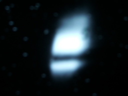
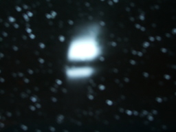
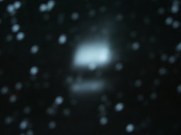
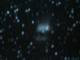
- After get beam back observe that there is a significant "burn" strip across lower portion of the primary mirror
- Image #1 of primary mirror damage at 23W synch light monitor:
- Image #2:
- Image #3:
- Image #4:
- Image #5 after adjusting VBUMPING 23 +253 CU:
- Determine that 253 units of VBUMPING 23 results in vertical center of beam being located halfway between "burn" strip and top edge of mirror. Probably the best operating point we can aim for.
- Get reasonable image with:
- CSRSYLTE CON 1 (Horz) = 602
- CSRSYLTE CON 2 (Vert) = 493
- CSRSYLTOUCHY 1 (Horz) = 514
- CSRSYLTOUCHY 2 (Vert) = 563
- 1245 - 1345 - Turn over to GWC for feedback checks
- 1345 - 1430 - Access to move target
- Place target on bunch-by-bunch optics line before filter/lens assembly
- 1430 - 1515 - Check alignment further
- Optimize mirrors for CCD signal and obtain:
- CSRSYLTE CON 1 (Horz) = 812 (LIMIT)
- CSRSYLTE CON 2 (Vert) = 468
- CSRSYLTOUCHY 1 (Horz) = 414
- CSRSYLTOUCHY 2 (Vert) = 598
- Bunch-by-bunch optics line shows beamspot low by 3/16 inch and to radial outside of ring by 1/16 inch. OK!
- 1515 - 1530 - Let DLR run a couple tests for USPAS
- 1530 - 1630 - Set up for optics box realignment
- Set up periscope and laser
- Adjust horizontal periscope until CSRSYLTE CON 1 no longer at limit
- Able to center laser beam on TV reticle and have symmetric working region in both horizontal and vertical with new settings
- Nominal mirror settings for centered laser spot:
- CSRSYLTE CON 1 (Horz) = 641
- CSRSYLTE CON 2 (Vert) = 470
- CSRSYLTOUCHY 1 (Horz) = 414
- CSRSYLTOUCHY 2 (Vert) = 597
- 1630 - 1800 - Turn over to MGB for magnet work
- 1800 - No e- for now so will continue checkout tomorrow morning
--
MarkPalmer - 20 Jun 2005
June 21, 2005 (M. Palmer, E. Tanke)
- 0830 - Quick check for light appears OK. Unable to see bunch-by-bunch signal, however. After power cycling DSP were able to see noise but no signal.
- 0900 - Access. Appeared to have a poorly seated signal connector. Checked bunch optics rail alignment by laser and adjust so that beam is approximately on axis for CCD beamspot near center of CCD mirror and
- 1200 - Load electrons for bunch-by-bunch readout test and CCD optimization. Set VBUMPING 23 to 253 CU so that beamspot between burn strip and top edge of mirror.
- Find that a good CCD operating point is with the following settings:
- CSRSYLTE CON 1 (Horz) = 700
- CSRSYLTE CON 2 (Vert) = 463
- CSRSYLTOUCHY 1 (Horz) = 384
- CSRSYLTOUCHY 2 (Vert) = 604
- This setting has the camera image on center vertically and 2mm to the left horizontally
- Bunch-by-bunch readout is now operational
- Find good BSM performance with the camera image 7mm to the left of center (ie, towards outside of ring). The mirror controls are at:
- CSRSYLTE CON 1 (Horz) = 709 <---- Only difference from CCD
- CSRSYLTE CON 2 (Vert) = 463
- CSRSYLTOUCHY 1 (Horz) = 384
- CSRSYLTOUCHY 2 (Vert) = 604
- Stored 2 sets of measurements for e+= 0 mA, e-= 80 mA with timing set to 840 and HV=-550V:
- Averaged data (test_300avg)-> 2005_06_21/1247/BSM_PAW_2005_06_21_1247.DAT
- 1000 turn raw data (test_10kraw)-> 2005_06_21/1251/BSM_PAW_2005_06_21_1251.DAT
- 1250 - Start short access to finish alignment of bunch-by-bunch optics rail. Want to try to get within a mm of optimum CCD alignment.
- Had a brief scare in that left PMT HV on when tunnel lights activated
- Use laser to check alignment and adjust bunch-by-bunch optics rail
- 1315-1445 Unable to run due to magnet run-up problems and chopper failure
- 1445-1515 Play mirror settings off against each other in order to set up centered working point for CCD and BSM.
- Find good performance with the following settings (saveset taken: 103554):
- VBUMPING 23 = 253
- CSRSYLTE CON 1 (Horz) = 700
- CSRSYLTE CON 2 (Vert) = 466
- CSRSYLTOUCHY 1 (Horz) = 376
- CSRSYLTOUCHY 2 (Vert) = 609
- Observe that CCD vertical size numbers vary from approximately 180 to 215 microns as adjust mirror setup and position on CCD. The above settings gave a size around 200 microns.
- Stored 2 sets of measurements for e+= 0 mA, e-= 80 mA with timing set to 840 and HV=-520V (notice change in HV):
- Averaged data (test_300avg)-> 2005_06_21/1509/BSM_PAW_2005_06_21_1509.DAT
- 1000 turn raw data (test_10kraw)-> 2005_06_21/1513/BSM_PAW_2005_06_21_1513.DAT
- 1515 - Transition to single-turn orbit and pulsed bump setup studies (MGB/JAC)
- Bunch measurement results are shown in: MS2005_06_21.pdf
--
MarkPalmer - 21 Jun 2005
June 22, 2005 (M. Palmer, E. Tanke) Changes to Electron Synch Light Box Beamsplitters at 23W
- 0730 - Ready for access to install alternate beamsplitters in electron synch light. However have to wait for checkout of ground fault on West Quad Meeker during magnet rampdown.
- 0745 to 1000 - Replace beamsplitters in optics box
- First verify distance between expander lens and PMT face as 8 1/8 inches
- Then set up laser and targets as reference points for beamsplitter replacement
- Prepare to replace two 8R/92T beamsplitters (one to pick of light for camera/PMT before CCD, and second to pick of light for PMT before camera) with 50R/50T beamsplitters
- Nominal light fractions
| Optics Line | Before | After |
| CCD | 92% | 50% |
| PMT | 0.64% | 25% |
| TV Camera | 7.4% | 25% |
- For the PMT line added a 12.5% ND filter before the PMT.
- Changes in position at the camera reticle versus the CCD appear to be at the +/-1mm level
- Had to readjust PMT optics line and may have bigger errors there.
- 1310 - Start alignment checks
- Find good CCD alignment (with VBUMPING 23 = 253 CU) with
- CSRSYLTE CON 1 (Horz) = 695
- CSRSYLTE CON 2 (Vert) = 467
- CSRSYLTOUCHY 1 (Horz) = 383
- CSRSYLTOUCHY 2 (Vert) = 607
- The spot on the camera reticle is 1mm above center and 2.5 mm to outside of ring (ie, left) in the horizontal. Take saveset 103573.
- Observe very low single bunch PMT signal which is rather confusing. Ultimately run PMT to -680V and find that the centered position on the PMT is 3mm above center and 2.5mm to inside of ring on the camera reticle.
- Check of removed beamsplitters
- After unexpected light levels, re-inspect beamsplitters removed during this morning's access. Beamsplitter in front of CCD was apparently NOT an 8R/92T beamsplitter but rather a 33R/67T or 50R/50T beamsplitter (difficult to tell the difference without an intensity measurement setup). Assuming the former, this means that the nominal light fraction changes should be:
| Optics Line | Before (nominal) | After (nominal) | Ratio (nominal) |
| CCD | 67% | 50% | 0.75 |
| PMT | 33% x 8% = 2.6% | 50% x 50% x 12.5% = 3.1% | 1.2 |
| TV Camera | 33% x 92% = 30.4% | 50% x 50% = 25% | 0.82 |
- For the 50R/50T case this would be:
| Optics Line | Before (nominal) | After (nominal) | Ratio (nominal) |
| CCD | 50% | 50% | 1.0 |
| PMT | 50% x 8% = 4% | 50% x 50% x 12.5% = 3.1% | 0.78 |
| TV Camera | 50% x 92% = 46% | 50% x 50% = 25% | 0.54 |
- The above is closer to what we observed but still seems to overestimate the observed PMT signal. Expect that the spectral response of the coated versus uncoated pellicles in combintation with the spectral response of each device is complicating the issue. Will need to investigate further during access on 6/23. Will also attempt to calibrate CCD response from before and after as an additional cross-check.
--
MarkPalmer - 22 Jun 2005
June 23, 2005 (M. Palmer, E. Tanke) Bunch-by-Bunch Optics Line for Electron Synch Light Box at 23W
- 1000 - During access removed the ND filter from the bunch-by-bunch optics line
- 1200 - SBP recovered injection so that we can check BSM response to 2mA T1B1 e-
- Find good CCD alignment (with VBUMPING 23 = 253 CU) at:
- CSRSYLTE CON 1 (Horz) = 692
- CSRSYLTE CON 2 (Vert) = 467
- CSRSYLTOUCHY 1 (Horz) = 382
- CSRSYLTOUCHY 2 (Vert) = 608
- Search for BSM signal
- First observe a very small signal of approx 200 ADC counts at 500 V
- Initial signal moves when vertically scan
- Do a LARGE horizontal scan and finally realize that we must have messed up the optics rail alignment yesterday. Real BSM signal requires a 15-20 mm displacement from center of TV reticle. Real signal is 100x larger!!!
- 1230 - 1330 Turn over to DLR for USPAS studies
- 1330 - Access in magnet bypass mode with MGB
- 9 minute access allows us to rotate the BSM optics rail around the pellicle and displacing the PMT approx 1 cm to the radial inside of the ring.
- Upon putting 2 mA T1B1 e- in mahcine and maximizing PMT signal, find the following:
| PMT HV | Signal Level (16 x ADC) |
| -400 | 13000 |
| -420 | 19800 |
| -450 | 30500 |
| -460 | 35000 |
| -470 | 40000 |
| -480 | Saturation |
- Verified that single turn profiles could be obtained with this setup
- Final alignment has CCD and BSM optimum points off by about 2mm horizontally. Optimized BSM output (with VBUMPING 23 = 253 CU) at:
- CSRSYLTE CON 1 (Horz) = 734 --> 729 (for good CCD performance)
- CSRSYLTE CON 2 (Vert) = 466
- CSRSYLTOUCHY 1 (Horz) = 339
- CSRSYLTOUCHY 2 (Vert) = 608
- Stored 1 set of measurements for e+= 0 mA, e-= 2 mA (T1B1 only) with timing set to 900 and HV=-450V :
- 10000 turn raw data (test_10kraw)-> 2005_06_23/1402/BSM_PAW_2005_06_23_1402.DAT
- Bunch measurement results are shown in: MS2005_06_23.pdf
- A quick check of the BSM23W PMT response was made:
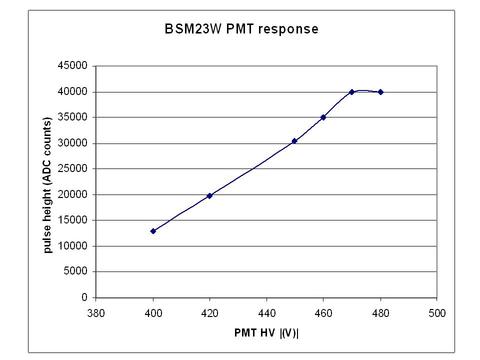
--
MarkPalmer - 23 Jun 2005
June 24, 2005 (M. Palmer, E. Tanke) Bunch-by-Bunch Optics Line for Electron Synch Light Box at 23W
- Stored 4 set of measurements for T1B1 only, with timing set to 900 in the following subdirectories of /home/tanke/cesr/ts101/bsm23w/test_10kraw :
- 80000 turn raw data, 1.9 mA, HV=-500V, taken with test_10kraw at 08:05 -> 2005_06_24/0805/BSM_PAW_2005_06_24_0805.DAT
- 125000 turn raw data, 1.6 mA, HV=-470V, taken with test_10kraw at 12:13 -> 2005_06_24/1213/BSM_PAW_2005_06_24_1213.DAT
- 125000 turn raw data, 1.6 mA, HV=-470V, taken with test_10kraw at 13:00 -> 2005_06_24/1300/BSM_PAW_2005_06_24_1300.DAT
- 125000 turn raw data, 1.6 mA, HV=-470V, taken with test_10kraw at 14:35 -> 2005_06_24/1435/BSM_PAW_2005_06_24_1435.DAT
- Bunch measurement results are shown in: MS2005_06_24.pdf
- Details of the experimental setup can be found on the CESR Machine Studies page
--
EugeneTanke - 24 Jun 2005
June 25, 2005 (M. Palmer, E. Tanke) Bunch-by-Bunch Optics Line for Electron Synch Light Box at 23W
- Measurement for T1B1 only, whereby the acquisition was triggered by the second bit ( = bit 1 ) of the GLOBAL_TURN_DAT trigger word. Stored measurement, with timing set to 900, in /home/tanke/cesr/ts101/bsm23w/test_10kraw/2005_06_25 :
- 125000 turn raw data, 4.2 mA, HV=-460V, taken with test_10kraw at 22:22 -> BSM_PAW_2005_06_25_2222.DAT
- Bunch measurement results are shown in: MS2005_06_25.pdf
--
EugeneTanke - 25 Jun 2005
June 27, 2005 (M. Palmer, M. Billing, E. Tanke, A. Wolski) Damping Studies
- Details of today's experimental setup can be found on today's CESR Machine Studies page
- Measuruments are for T1B1 e- with PMT HV=-500V, DSP timing=900 (unless noted otherwise)
- Data is stored in /home/tanke/cesr/ts101/bsm23w/test_10kraw
- 2005_06_27/1649 data, 1.9 mA
- 10K turns taken away from resonance with no pulsed elements on to get a baseline; triggered by the second bit ( = bit 1 ) of the GLOBAL_TURN_DAT trigger word.
- 2005_06_27/1654 data, 1.9 mA
- 10K turns taken near resonance with pulsed elements on; triggered by the second bit of GLOBAL_TURN_DAT.
- 2005_06_27/1702 data, 1.86 mA
- Same conditions as 1654 but with pulsed elements off; triggered by the second bit of GLOBAL_TURN_DAT.
- 2005_06_27/1727 data, 1.7 mA
- Triggered by the first bit ( = bit 0 ) of GLOBAL_TURN_DAT.
- 2005_06_27/1731 data, 1.7 mA
- Triggered by the first bit ( = bit 0 ) of GLOBAL_TURN_DAT.
- 2005_06_27/1736 data, 1.7 mA
- Triggered by the first bit ( = bit 0 ) of GLOBAL_TURN_DAT.
- 2005_06_27/1809 data, 1.6 mA
- 125K turns; triggered by the second bit ( = bit 1 ) of GLOBAL_TURN_DAT.
- 2005_06_27/1853 data, 1.15 mA
- 125K turns; triggered by the second bit ( = bit 1 ) of GLOBAL_TURN_DAT.
- 2005_06_27/2131 data, 1.98 mA
- 125K turns; triggered by the second bit ( = bit 1 ) of GLOBAL_TURN_DAT.
- 2005_06_27/2218 data, 1.7 mA
- 125K turns; triggered by the second bit ( = bit 1 ) of GLOBAL_TURN_DAT in single shot mode.
- 2005_06_27/2303 data, 1.6 mA
- 125K turns; triggered by the second bit ( = bit 1 ) of GLOBAL_TURN_DAT in single shot mode.
- 2005_06_27/2348 data, 0.4 mA, PMT HV= -590 V
- 125K turns; triggered by the second bit ( = bit 1 ) of GLOBAL_TURN_DAT in single shot mode.
June 28, 2005 (M. Palmer, M. Billing, E. Tanke, A. Wolski) Damping Studies
- Continuation of last night's damping studies
- 2005_06_28/0040 data, 1.5 mA
- 125K turns; triggered by the second bit ( = bit 1 ) of GLOBAL_TURN_DAT in single shot mode.
July 2005
July 8, 2005 (E. Tanke) Testing of BSM
- Testing BSM with test programs compiled under Visual DSP V4 :
- [.test_sram]get_sram --> passed
- [.test_registers]get_registers.com --> passed
- [.test_registers]PATM_TEST_V4 --> passed
- [.test_controls]PAT_PATM_TEST_V4 --> passed
- [.test_controls]VEC_PAT_PST_TEST --> passed
- [.test_adcbuf]get_adcbuf --> passed
- [.test_adcbuf]get_adcbuf_err --> passed
- [.test_daq]GET_AVGS --> passed
- [.test_daqmb]GET_AVGSMB --> passed
- [.test_daqpack]GET_PACK --> passed
- [.test_10kraw]get_10kraw --> passed
- [.test_300avg]get_300avg --> passed
- All channels function; a more detailed test, using update_300avg, will still need to be conducted in order to better compare pulseheights from one channel to the next.
--
EugeneTanke - 08 Jul 2005
July 13, 2005 (M. Palmer, E. Tanke) Testing of TEST_SUM10 on BSM23W
- In view of future damping studies, a test was made with TEST_SUM10, a DSP program that will sum ADC counts for 10 bunches. The output file contains the following for columns:
- Column 1: turn number
- Column 2: ADC channel number
- Column 3: sum of the ADC counts for the 10 bunches
- Column 4: ADC counts for the pedestal
- This test run was for all 32 channels, timing set to 900, PMT HV=-620V, 47000 turns, e- = 180 mA, e+ = 149 mA and free running (no specific trigger used). Bunches selected were T1B1...T1B5 and T2B1...T2B5; the pedestal selected was T1B14. Results are stored on the file server in the tanke/cesr/ts101/bsm23w/test_sum10/2005_07_13 directory in file:
- BSM_PAW_2005_07_13_1055.DAT
July 19, 2005 (M. Palmer, M. Billing, E. Tanke) Damping Studies and Checks of CHESS Conditions
- Details of today's experimental setup can be found on today's CESR Machine Studies page
- Measuruments are for T1B1 e- with PMT HV=-500V, DSP timing=900; measurements WITHOUT neutral density filter.
- Data is stored in /home/tanke/cesr/ts101/bsm23w/test_10kraw under:
- 2005_07_19/1620 Data for 2.1 mA
- 50K turns taken with separators off; free running (GLOBAL_TURN_DAT trigger word not used).
- 2005_07_19/1655 Data for 2.1 mA
- 50K turns taken with separators on; free running (GLOBAL_TURN_DAT trigger word not used).
- 2005_07_19/1734 Data for 1.8 mA
- 125K turns; triggered by the second bit ( = bit 1 ) of GLOBAL_TURN_DAT.
- 2005_07_19/1818 Data for 1.7 mA
- 50K turns; triggered by the second bit ( = bit 1 ) of GLOBAL_TURN_DAT.
- 2005_07_19/1900 Data for 2.1 mA
- 125K turns; triggered by the second bit ( = bit 1 ) of GLOBAL_TURN_DAT.
- 2005_07_19/1943 Data for 2.1 mA
- 50K turns; triggered by the first bit ( = bit 0 ) of GLOBAL_TURN_DAT.
- 2005_07_19/2005 Data for 2.0 mA
- 50K turns; triggered by the first bit ( = bit 0 ) of GLOBAL_TURN_DAT.
- After these measuruments the neutral density filter was reinstalled.
July 20, 2005 (M. Palmer, E. Tanke) Measurements under CHESS conditions
- Measuruments are for T1B1 e- with DSP timing=900; measurements with neutral density filter. e- = 201 mA, e+ = 154 mA.
- Data are stored in /home/tanke/cesr/ts101/bsm23w/test_10kraw
- 2005_07_20/1008 Data with PMT HV= -500V, e- = 201 mA, e+ = 154 mA, 50K turns; free running (GLOBAL_TURN_DAT trigger word not used).
- 2005_07_20/1030 Data with PMT HV= -620V, e- = 198 mA, e+ = 150 mA, 50K turns; free running (GLOBAL_TURN_DAT trigger word not used).
- These data have low pulse height; verification with "realtime" program shows pulseheight > 20000 (which is expected). Repeat the measurement:
- 2005_07_20/1102 Data with PMT HV= -620V, e- = 193 mA, e+ = 145 mA, 50K turns; free running (GLOBAL_TURN_DAT trigger word not used).
- Measurement with TEST_SUM10 (sum ADC counts for 10 bunches) for all 32 channels, timing set to 900, PMT HV=-620V, 47000 turns, e- = 201 mA, e+ = 157 mA and free running (no specific trigger used). Bunches selected were T1B1...T1B5 and T2B1...T2B5; the pedestal selected was T1B14. Results are stored on the file server in tanke/cesr/ts101/bsm23w/test_sum10/
- Measurement of raw data for the same bunches and under the same conditions as the previous TEST_SUM10 measurement. Data took ~80 minutes to transfer and it took ~5 minutes to write the data file. Data are stored in /home/tanke/cesr/ts101/bsm23w/test_10kraw under:
- 2005_07_20/1725 Data with PMT HV= -620V, e- = 193 mA, e+ = 148 mA, 47K turns; free running (GLOBAL_TURN_DAT trigger word not used).
July 21, 2005 (M. Palmer, E. Tanke) Measurements under CHESS conditions
- Measurument for T1 and T2 e- bunches with DSP timing=900. Note that with the neutral density filter in and with a typical fill of 200 mA electrons and 150 mA protons, setting the PMT HV= -520V yields 15-20 mV pulseheight on the PMT (20 mV is the maximum under these conditions). Data are stored in /home/tanke/cesr/ts101/bsm23w/test_10kraw under
- 2005_07_21/1044 data with PMT HV= -520V, e- = 187 mA, e+ = 143 mA, 20K turns; free running (GLOBAL_TURN_DAT trigger word not used).
July 26, 2005 (M. Palmer, E. Tanke, A. Wolski) Single bunch damping studies with BSM23W
- Measuruments are for T1B1 e- only, DSP timing=900; measurements without neutral density filter, PMT HV= -530V
- Data are stored in /home/tanke/cesr/ts101/bsm23w/test_10kraw under
- 2005_07_26/1700 data with e- = 2.0 mA, 50K turns; free running (GLOBAL_TURN_DAT trigger word not used); baseline
- 2005_07_26/1720 data with e- = 2.0 mA, 125K turns; triggered by the second bit ( = bit 1 ) of GLOBAL_TURN_DAT; pinger on
- previous data set corrupted (see MS log).
- 2005_07_26/1825 data with e- = 2.0 mA, 125K turns; triggered by the second bit ( = bit 1 ) of GLOBAL_TURN_DAT
- 2005_07_26/1917 data with e- = 2.0 mA, 125K turns; triggered by the second bit ( = bit 1 ) of GLOBAL_TURN_DAT
- Details of today's experimental setup can be found on today's CESR Machine Studies page
August 2005
August 1, 2005 (E. Tanke) Pulse height test with BSM
- Each of the 32 channels of BSM was tested with a signal from a pulse generator in order to compare channel to channel pulse heights. In this test raw data were taken at the timing corresponding to the location of the peak; these data were then averaged over 3 periods of 60 Hz. Results are shown in BSM2PHs.pdf
August 2, 2005 (M.Palmer, C.Strohman, J.Dobbins, A. Wolski, E. Tanke) BSM23W work and MS
- A repeater was installed on the timing that triggers BSM23W and the signal quality was verified to have improved w.r.t. last week's finding.
- The ND filter was taken out in view of today's MS
- Details of today's experimental setup can be found on today's CESR Machine Studies page
- Modified card timings in test_10kraw.c and test_300avg.c due to installation of repeater:
- Old timings for card 0..3: 100,100,100,100
- New timings for card 0..3: 1023,978,1023,1023
- Measurument 2256 for T1B1 e- only, DSP timing=685; measurement without neutral density filter, PMT HV= -530V; data stored in /home/tanke/cesr/ts101/bsm23w/test_10kraw under
- 2005_08_02 data with e- = 1.27 mA, 125K turns; triggered by the second bit ( = bit 1 ) of GLOBAL_TURN_DAT; V pinger on
August 18, 2005 (E. Tanke) Verification of BSM23W timing
- The measurement taken on August 2, 2005 contains many "spurious" data. It was found that this is due to the fact that one should not change the card timings by more than +/- 100 w.r.t. the nominal 100.
- The timing scan program, which had been artificially limited in software to a global timing range of 0..1500, has been modified and now has as global timing range 0..2047
- The measurement taken on August 2, 2005 seemed to indicated a problem with geometric channel 16 (1..32). This turned out to be part and parcel of the consequences of having bad card timing settings as confirmed by todays measurement of 162 mA e- only, using get_10kraw with card timings at 100, global timing at 1620, PMT HV= -490V. Data stored in tanke/cesr/ts101/bsm23w/test_10kraw/2005_08_18
September 2005
September 14 , 2005 (M. Billing, M.Palmer, E. Tanke) BSM23W work and MS
- Measurment with the 5 bunches of train 1 (plus one pedestal) with total currents: e-=7 mA, e+=0 mA. Timing set to 1560 with card timings set to 100. PMT HV=640 V, neutral density filter in place. 75k turn data stored in file 1608 in /home/tanke/cesr/ts101/bsm23w/test_10kraw/2005_09_14
September 15 , 2005 (M. Billing, M.Palmer, E. Tanke) BSM23W work and MS
- Measurment with the 5 bunches of train 1 (plus one pedestal) with total currents: e-=8.2 mA, e+=0 mA. Timing set to 1560 with card timings set to 100. PMT HV=640 V, neutral density filter in place. 40k turn data stored in /home/tanke/cesr/ts101/bsm23w/test_10kraw/2005_09_15 in:
- sub-directory O929 (synchrotron on, seperators on)
- sub-directory 1O07 (synchrotron off, seperators off)
September 21 , 2005 (M. Billing, M.Palmer, E. Tanke) BSM23W work and MS
- Machine study hampered by the fact that timings seemed to have changed: Time scans evidenced erratic behaviour for the old timings ( card timing = 100 and global timing = 1560 ). Non-erratic behaviour was found for card timing = 400 and Global timing 1200, whereby in order to acquire data from T1B1, we had to set the DSP to acquire from T9B21 (i.e. the preceding bunch).
- Measurment with a full load of beam, but looking at T1B1 with total currents: e-=0.8 mA, e+=0 mA. Timing set to 1200 with card timings set to 400. PMT HV=520 V, neutral density filter in place. 75k turn data stored in /home/tanke/cesr/ts101/bsm23w/test_10kraw/2005_09_21
September 28 , 2005 (M. Billing, M.Palmer, E. Tanke) BSM23W work and MS
- Testing get_navg with Tcards=400, Tglobal=1200, PMT HV=590V, T1B1 only, 1.7 mA of e- only; neutral density filter in place.
- 09:49 Baseline measurment with 100k turns, 100 turns/average; data stored in /home/tanke/cesr/ts101/bsm23w/test_navg/2005_09_28/0949
- 09:54 Baseline measurment with 100k turns, 25 turns/average; data stored in /home/tanke/cesr/ts101/bsm23w/test_navg/2005_09_28/0954
- 10:46 Measurement with open pulsed bump (approx 100 microsec) with strong quadrupoles, 100k turns, 25 turns/average; data stored in /home/tanke/cesr/ts101/bsm23w/test_navg/2005_09_28/1046
- 10:48 Raw data (test_10kraw) with puled bump, 100k turns; data stored in /home/tanke/cesr/ts101/bsm23w/test_10kraw/2005_09_28/1048/
- Measurement with test_navg, 100k turns, 100 turns/average, Tcards=400, Tglobal=1200, PMT HV=550V
- 15:41 Baseline measuement, stored in /home/tanke/cesr/ts101/bsm23w/test_navg/2005_09_28/1541
- 15:47 Measurement with pulsed bump, same settings as above, stored in /home/tanke/cesr/ts101/bsm23w/test_navg/2005_09_28/1547
- 15:58 Measurement with pulsed bump, same settings as above, stored in /home/tanke/cesr/ts101/bsm23w/test_navg/2005_09_28/1558
- 16:04 Measurement with shake (125k turns raw data), same settings, using HW trigger mask=1 (i.e. trigger bit 0 set); stored in /home/tanke/cesr/ts101/bsm23w/test_10kraw/2005_09_28/1604
- Neutral density filter has been taken out (16:55), PMT HV= 430V, with T1B1 e- only at 2.9 mA yields 22500 pulse height
- 16:59 Measurement with pulsed bump, vertical feedback on, stored in /home/tanke/cesr/ts101/bsm23w/test_navg/2005_09_28/1659
- 17:07 Measurement with pulsed bump, vertical feedback off (125k turns, 100 turns/avg , stored in /home/tanke/cesr/ts101/bsm23w/test_navg/2005_09_28/1707
- 17:10 Repeat of 17:07 stored in /home/tanke/cesr/ts101/bsm23w/test_navg/2005_09_28/1710
- 17:14 Measurement with pulsed bump, vertical feedback on, stored in /home/tanke/cesr/ts101/bsm23w/test_navg/2005_09_28/1714
- Lowered the beam current (CERN) to 0.98 mA;
- 17:19 Measurement with pulsed bump, vertical feedback on, stored in /home/tanke/cesr/ts101/bsm23w/test_navg/2005_09_28/1719
- 17:23 Idem, but with PMT HV= 470 V, stored in /home/tanke/cesr/ts101/bsm23w/test_navg/2005_09_28/1723
- 17:25 Repeat of 17:23, stored in /home/tanke/cesr/ts101/bsm23w/test_navg/2005_09_28/1725
- 17:27 Idem, but with 250k turns and 100 turns/average, stored in /home/tanke/cesr/ts101/bsm23w/test_navg/2005_09_28/1727
- 17:30 Idem, but with 125k turns and 25 turns/average, stored in /home/tanke/cesr/ts101/bsm23w/test_navg/2005_09_28/1730
- Lowered the beam current (CERN) to 0.52 mA; 250k turns and 100 turns/average
- 17:35 Measurement stored in /home/tanke/cesr/ts101/bsm23w/test_navg/2005_09_28/1735
- 17:38 Repeat of 17:35, stored in /home/tanke/cesr/ts101/bsm23w/test_navg/2005_09_28/1738
- 17:41 Repeat of 17:35, stored in /home/tanke/cesr/ts101/bsm23w/test_navg/2005_09_28/1741
- Lowered the beam current (CERN) to 0.23 mA; PMT HV=470 V
- 17:44 Measurement stored in /home/tanke/cesr/ts101/bsm23w/test_navg/2005_09_28/1744
- 17:49 Baseline, no bump, PMT HV=520 V, stored in /home/tanke/cesr/ts101/bsm23w/test_navg/2005_09_28/1749
- 17:52 Bump on, stored in /home/tanke/cesr/ts101/bsm23w/test_navg/2005_09_28/1752
- 17:54 Repeat of 17:52, stored in /home/tanke/cesr/ts101/bsm23w/test_navg/2005_09_28/1754
- 17:56 Repeat of 17:52, stored in /home/tanke/cesr/ts101/bsm23w/test_navg/2005_09_28/1756
- 18:00 Raw data over 125k turns, using HW trigger mask=1 (i.e. trigger bit 0 set); stored in /home/tanke/cesr/ts101/bsm23w/test_10kraw/2005_09_28/1800
- Neutral density filter has been reinstalled at 18:15
October 2005
October 05 , 2005 (M.Billing, M.Palmer, M.Watkins, E.Tanke) BSM23W MS: tune wobble measurements (single e- bunch T1B1)
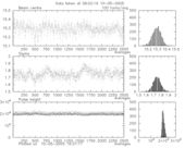
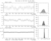
- Tune wobble measurements with test_navg, 250k turns, 100 turns/average, Tcards=400, Tglobal=1200, PMT HV=560V
- 08:02 Measurement with 2.2 mA of e-, stored in /home/tanke/cesr/ts101/bsm23w/test_navg/2005_10_05/0802
-
- 08:16 Measurement with 2.2 mA of e-, stored in /home/tanke/cesr/ts101/bsm23w/test_navg/2005_10_05/0816
-
- 08:23 Measurement with 2.1 mA of e-, stored in /home/tanke/cesr/ts101/bsm23w/test_navg/2005_10_05/0823
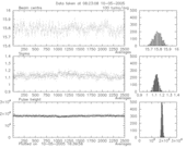
-
- 08:30 Measurement with 2.1 mA of e-, stored in /home/tanke/cesr/ts101/bsm23w/test_navg/2005_10_05/0830
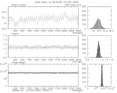
-
- 08:59 Measurement with 2.2 mA of e-, stored in /home/tanke/cesr/ts101/bsm23w/test_navg/2005_10_05/0859
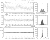
- M.Billing installed jumper #1; apart from PMT HV=550V, conditions as above; new tune wobble measurements:
- 10:11 Measurement with 2.9 mA of e-, stored in /home/tanke/cesr/ts101/bsm23w/test_navg/2005_10_05/1011
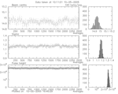
-
- 10:23 Measurement with 2.7 mA of e-, stored in /home/tanke/cesr/ts101/bsm23w/test_navg/2005_10_05/1023
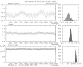
-
- 10:40 Measurement with 2.5 mA of e-, stored in /home/tanke/cesr/ts101/bsm23w/test_navg/2005_10_05/1040
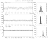
-
- 10:49 Measurement with 2.5 mA of e-, stored in /home/tanke/cesr/ts101/bsm23w/test_navg/2005_10_05/1049
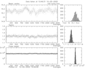
- M.Billing installed jumper #2; apart from PMT HV=550V, conditions as above; new tune wobble measurements:
- 11:26 Measurement with 2.8 mA of e-, stored in /home/tanke/cesr/ts101/bsm23w/test_navg/2005_10_05/1126
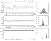
October 09 , 2005 (M.Palmer, E.Tanke) BSM23W beam size measurements (to compare with FLM measurements)
- Measurements with test_300avg, 100 loops, 1000 turns, Tcards=400, Tglobal=1200, PMT HV=470V
- Note that, because of the recently installed timing repeater, bunch data got shifted by one bunch. For the PAW analysis, a new kumac (read_avg_data_m.kumac) was created in order to read the bunch data correctly.
- 23:46 Measurement stored in /home/tanke/cesr/ts101/bsm23w/test_300avg/2005_10_09/2346, e-= 42 mA, e+= 75 mA
- 23:50 Measurement stored in /home/tanke/cesr/ts101/bsm23w/test_300avg/2005_10_09/2350, e-= 40 mA, e+= 74 mA
October 10 , 2005 (M.Palmer, E.Tanke) BSM23W beam size measurements (to compare with FLM measurements) (continued)
- Measurements with test_300avg, now PMT HV=550V
- 00:12 Measurement stored in /home/tanke/cesr/ts101/bsm23w/test_300avg/2005_10_09/0012, e-= 34 mA, e+= 67 mA
- 00:41 Measurement stored in /home/tanke/cesr/ts101/bsm23w/test_300avg/2005_10_09/0041, e-= 44 mA, e+= 76 mA
- 01:06 Measurement stored in /home/tanke/cesr/ts101/bsm23w/test_300avg/2005_10_09/0106, e-= 36 mA, e+= 68 mA
November 2005
November 10 , 2005 (E.Tanke) BSM23W timed in
- After 10-Oct-2005, a new timing repeater was installed in the tunnel. As a consequence, timing setings had to be re-established for the BSM.
- Beam conditions: 4x5 electrons 200 mA total (10 mA per bunch) and 4x5 positrons (non-colliding).
- With the PMT HV set to 400 V and after some mirror adjustment, a peak of ~3900 ADC counts was found for Tcard=100 and Tglob=1750.

 Copyright © by the contributing authors. All material on this collaboration platform is the property of the contributing authors.