Editing The Parts List In An Inventor Drawing
The Parts List in a drawing directly corresponds to the Bill of Materials in the related assembly. This procedure will demonstrate how to set up and edit the Bill of Materials, and how it affects the related drawing Parts List. To best show the possible situations and issues that you will encounter, and how to solve them, I will illustrate the process I use to create the Bill of Materials and Parts Lists for a drawing using 6029-030 as an example.
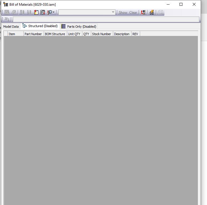
1.) First, I open the Bill of Materials from the assembly that I’m creating the parts list for, select the “Structured” tab, and if it’s Disabled, right click and select “Enable BOM View”.
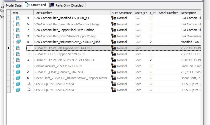
2.) I then need to organize the components in the assembly. The suggested method is assemblies first, then machined components, then purchased components, followed by hardware. (Hardware is usually organized by size, smallest to largest, followed by nuts, and then washers). There will be exceptions to this order, especially when a part is reused in multiple subassemblies, or when a part is added after a drawing is released. You can change the order of the components by clicking on the box at the left of the window with the black arrow and dragging the item up or down in the BOM.
3.) When the components are in the desired order, press the “Renumber Items” button at the top of the window.
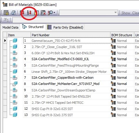
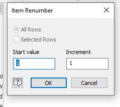
This can be done as many times as necessary until you are happy with the order. The top level assembly should always start with 1, but you can edit the start value when working in subassemblies.
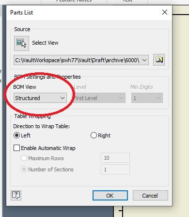
4.) When you are satisfied with the Bill of Materials, you can add it to your drawing by selecting “Parts List” from the “Annotate” tab and selecting a view for the assembly/subassembly that you are creating the parts list for. The parts list pop up window should be reading from the “Structured” BOM View.
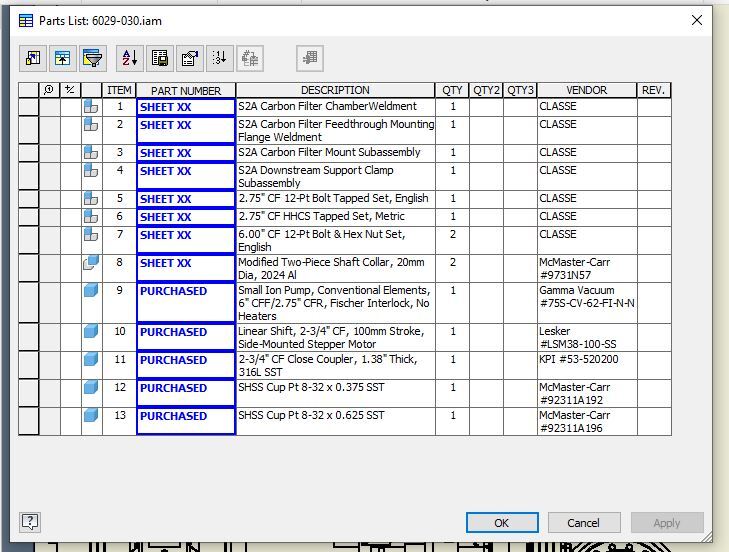
5.) If all of the iProperties are filled out properly in the models, the only column that you should need to edit is the Dwg. No. column. This is done by right clicking on the parts list in the drawing and selecting “Edit Parts List”. When the popup window appears, you can manually override the existing drawing number with either SHEET XX, if this item will appear in the drawing, or PURCHASED if it’s a purchased component. We will use a script later in the process to update the SHEET XX to the correct corresponding sheet number.
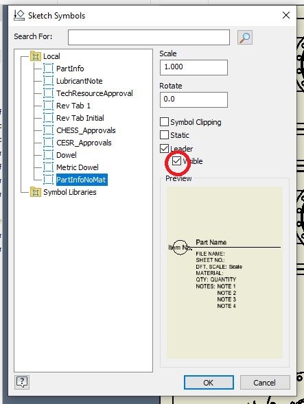
6.) After the Top Level Assembly and Parts List are added to the drawing, you can add subassemblies and components. In this example, I will add Items #1 and #2 to the next drawing sheet. (Use your own discretion to determine how many parts or assemblies should be on each sheet.) After you’ve added the views, you will add the part information. This is done by selecting “Insert Sketch Symbol” from the “Annotate” Tab. In this case, and the case of any assemblies, or parts where you want to add the material manually, select “PartInfoNoMat”. Be sure to uncheck the “Visible” box under “Leader”, or you will need to edit the symbol and uncheck it later.
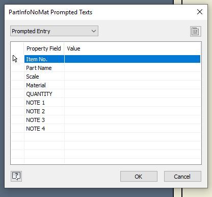
Then click on the assembly view where you want the leader to attach and then select the area on the drawing where you want the part information to appear. You will need to fill in the quantity, the material (if you want a material shown), and any notes from the Prompted Texts window. The script that we will run later will fill in the other necessary fields.
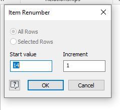
7.) The next step will be to update the Bill of Materials for the subassemblies. This is done the same way as shown in steps 1-3 with one exception. The item numbers will not start at 1. They will continue from the next highest available number, which in the case of this example is 14. Therefore, after I drag the items into the order I want, and select “Renumber Items” I will change the default Start Value from 1 to 14 for the first subassembly, and the process will be the same for subsequent assemblies using the next highest unused number.
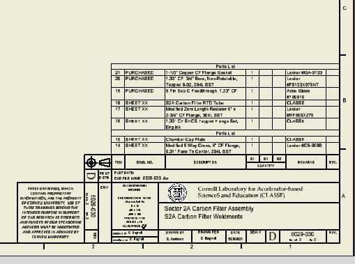
8.) After the subassemblies have been edited, and the Parts Lists have been created in the drawing, they should look like this.
9.) The next step would be to run the script that was mentioned earlier. Go to the “iLogic” tab in the browser window on the left of the Inventor window, expand “Scripts” and right-click “UpdatePromptedEntryNoMat” and select “Run Rule”. Click “Yes” on the pop-up window that comes up and the Part Info sketches will update automatically and so will the Parts List where these items are called out.
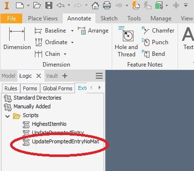
If for some reason, these scripts are not there, you can add them by right-clicking on “Manually Added” and selecting “Add External Rule”. These scripts are in the Vault under ~Vault/Draft/Scripts.
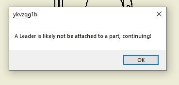
Also if you get the following error, check the drawing and make sure all of the invisible leaders are attached to the corresponding parts/assemblies or the script won’t work properly.
10.) For sheets with multiple assemblies, such as this example, I suggest labelling the Parts Lists. In order to do this, right-click the parts list and select “Edit Parts List”, then click the “Table Layout” button (circled in red below). When the Parts List Table Layout window pops up, I edit the title text by adding the item number in the assembly in parentheses followed by the description. (Example: Parts List (Item #2)
S2A Carbon Filter Feedthrough Mounting Flange Weldment)
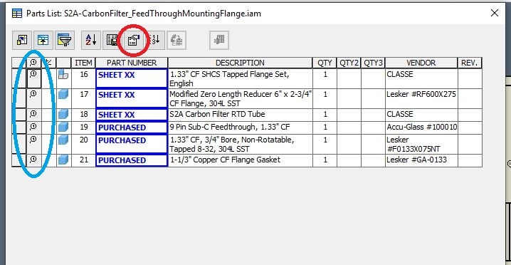
(Bonus Tip) When an item is ballooned in the assembly, it will show up in the column circled in blue above. This is a good way to double check that you have balloons for all the parts in your assembly.
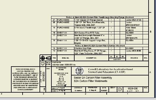
These are the completed parts lists for Items 1 & 2 in the example.
11.) At this point, I realized that the top level assembly was missing gaskets, so I added them to the assembly. I then dragged them to the proper location in the Bill of Materials, and hit the “Renumber Items” button. My Parts List on the drawing now looks like this.
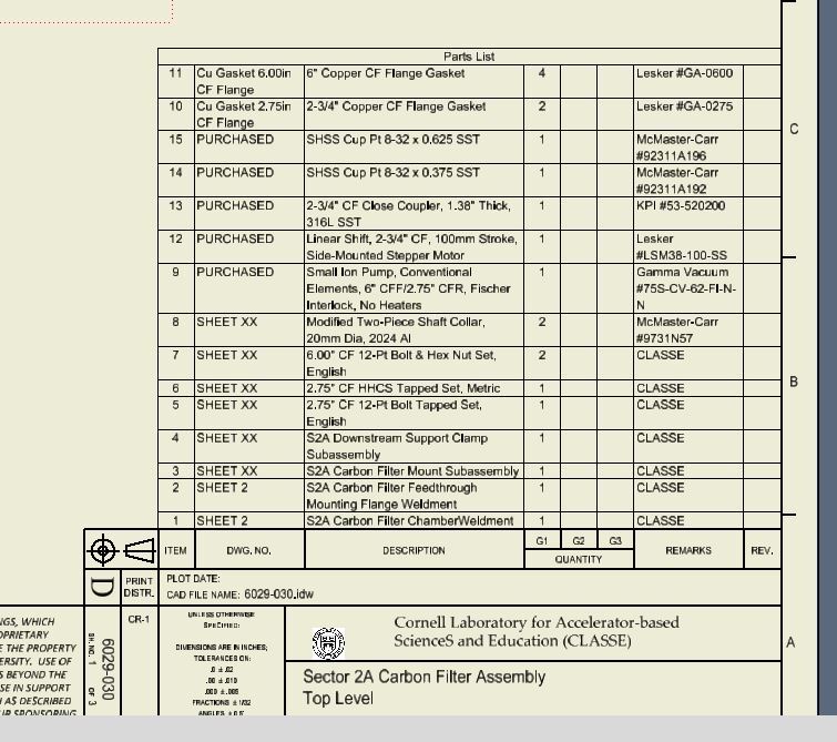
To solve this, I can right-click the parts list and select “Edit Parts List”, click the “Sort” button, and choose “Item” from the the “Sort By” pull down menu.
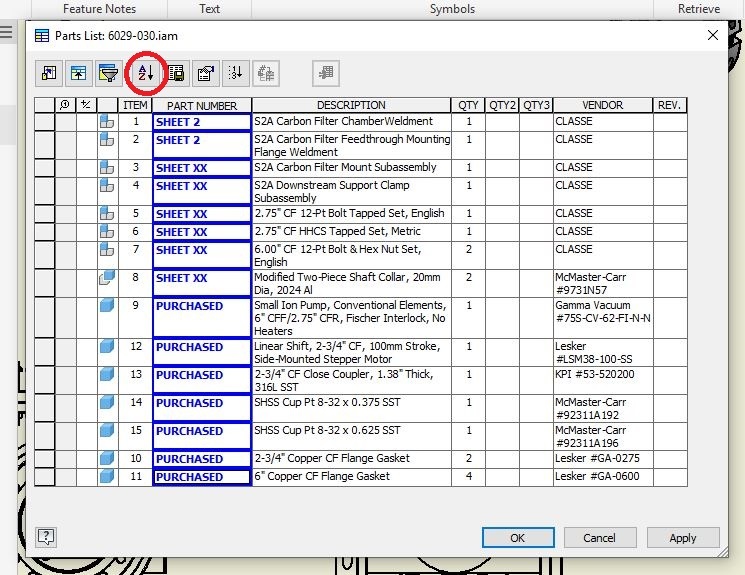
I then need to update the numbers in the Bill of Materials in the subsequent subassemblies. (Item one will now start from 16 instead of 14, and Item 2 will start from 18.)
12.) When I start to update the Bill of Materials for Item #3, I realize that I’ve already used two of the items in this subassembly in the top level assembly. I manually change the numbers of these two items to the the numbers that were previously assigned and renumber the remaining items starting with the next available number, which in this case is 24.
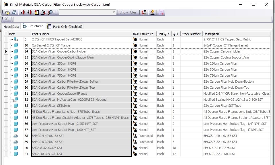
13.) I then follow the same procedure for the remaining subassembly, Item #4.
14.) When all of the subassemblies have been filled out and numbered, I start to add machined and modified components to the drawing. Each component needs to have a Part Info sketch attached to it. If the part is made from a standard material, the
PartInfo sketch should be used so that the material is automatically filled in. If the part is made from a modified purchased part or a non-standard material, the
PartInfoNoMat sketch should be used, so that the material can be entered manually. (Note that in some older drawings the
PartInfoNoMat sketch is named
PartInfo _NoMat. This should be renamed in the Drawing Resources/Sketch Symbols folder in order to work with the Scripts.) The quantity will need to be entered manually, all other fields will be filled in automatically when the Scripts are run (with the exception of the top level assembly, which will need to be filled out manually for every field.)
15.) After all components have been placed, and the sketches are attached, I open the iLogic tab and run the “UpdatePromptedEntry” and “UpdatePromptedEntryNoMat” scripts as explained in Step 9. This will update all of the
PartInfo sketches that I attached to the components as well as update the SHEET XX entries in the Parts Lists to the correct sheet number. This should be done on each drawing sheet to ensure that all sketches and parts lists are updated correctly.
16.) If you need to add a new component after the drawing is released, you can run the “HighestItemNo” Script from the iLogic tab, and it will open a window that lets you know the highest number used in the drawing you are in, and you can assign the new component the next highest number in the Bill of Materials/Parts List. This should always be done when adding a part to prevent using duplicate Item Numbers in the same assembly.
If you have any questions, comments, or concerns about this procedure, please contact Scott Hartman at swh77@cornell.edu.
--
ScottHartman - 11 Feb 2022
 ACC
ACC
 ACL
ACL
 Bunch
Bunch
 CBB
CBB
 NSF
NSF
 CBETA
CBETA
 CESR
CESR
 Private
 CHESS
CHESS
 FMB
FMB
 Maia
Maia
 XIMG
XIMG
 XLEAP
XLEAP
 CHEXS
CHEXS
 CLASSE
 Inventory
 CLEO
CLEO
 CMSPhase2MREFC
 Computing
 Blogs
Blogs
 Newsletter
 Cosmology
 DarkPhoton
 ERL
ERL
 EngineeringDesignDrafting
 G2
G2
 HEP
HEP
 DBSWorkshop
 SWIG
SWIG
 HLLHCCMSMREFC
 HMF
HMF
 HumanResources
 Private
 ILC
ILC
 Americas
 CesrTA
 Proposal
 DampingRings
 AreaLeaders
 CTA09
CTA09
 ILCDR06
 ILCDR07_KEK
 ILCDR08
 S3TaskForce
 WWS
WWS
 MacCHESS
 Main
Main
 People
 PhotocathodeBrightBeams
 REU
REU
 SRF
SRF
 Safety
 Sandbox
 TestWeb
 System
 Theory
 Communications
 Documents
 Phase2MREFC
 WebDev
 XLEAP
XLEAP
 Copyright © by the contributing authors. All material on this collaboration platform is the property of the contributing authors.